Gas inlet device and semiconductor machining device
A gas intake device and gas technology, which is applied in semiconductor/solid-state device manufacturing, electrical components, gaseous chemical plating, etc., can solve the problems of many process variables, heavy workload, and the influence of air flow uniformity, so as to improve process efficiency, The effect of increasing effectiveness and efficiency and improving the uniformity of airflow distribution
- Summary
- Abstract
- Description
- Claims
- Application Information
AI Technical Summary
Problems solved by technology
Method used
Image

Examples
no. 1 example
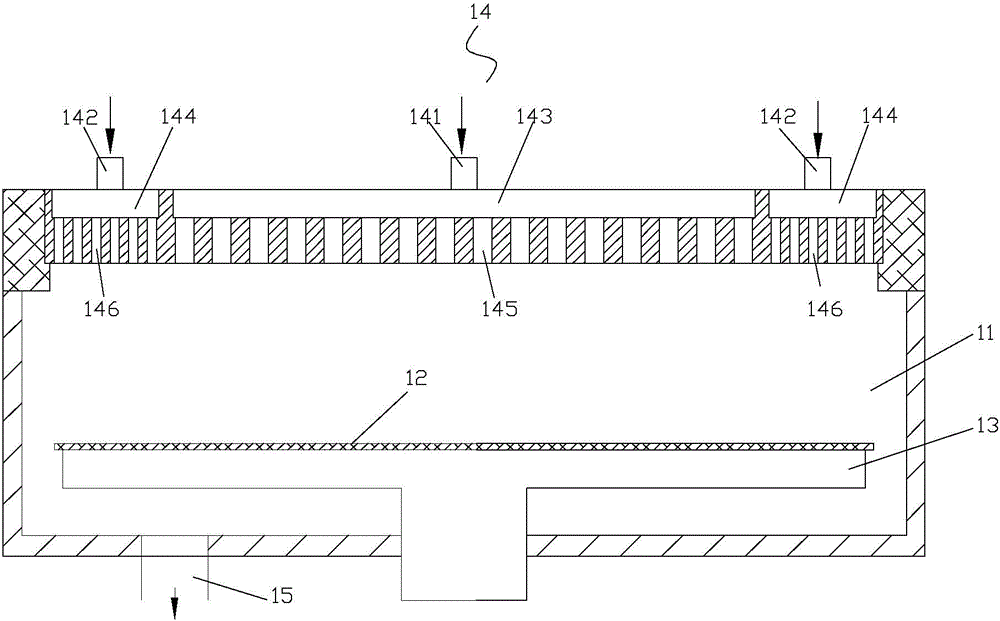
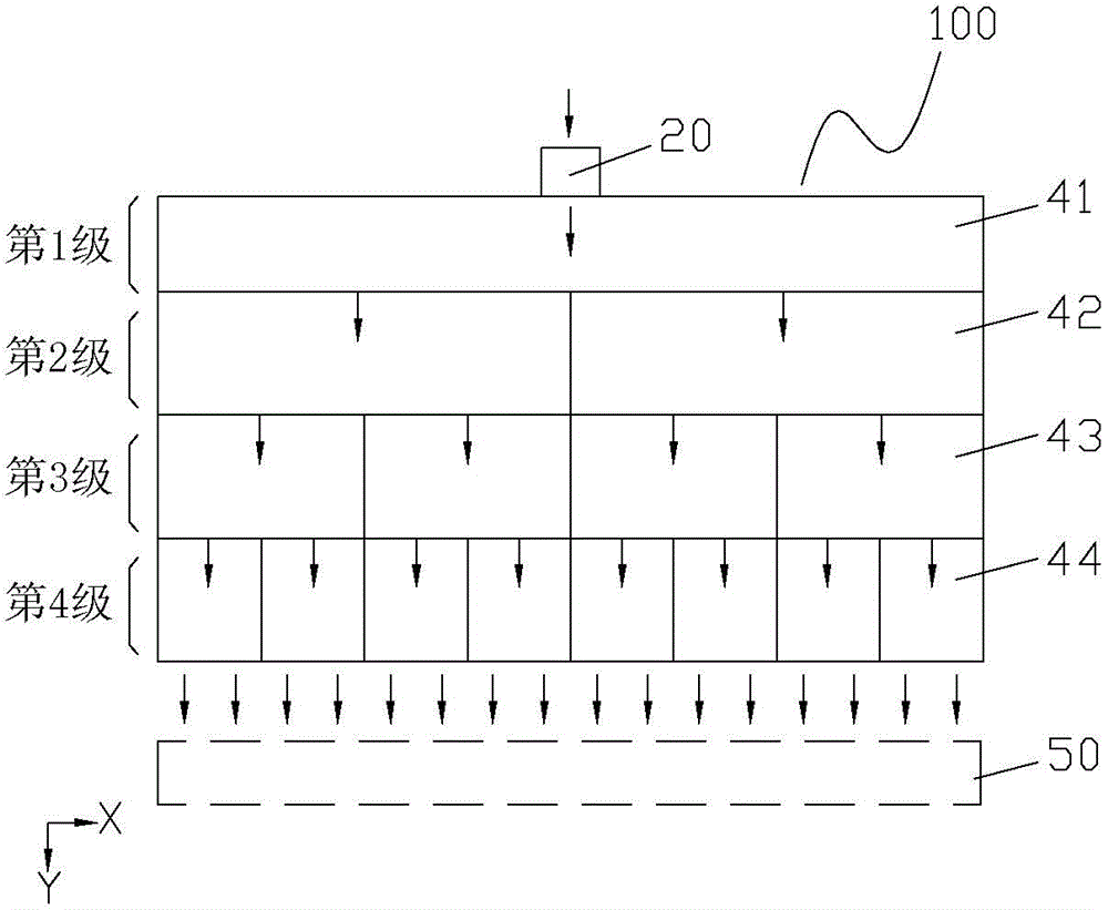
[0050] Figure 5A It is a schematic diagram of the air intake device provided by the first embodiment of the present invention. see Figure 5A , the air inlet device includes an air inlet 20 and an air inlet chamber 100, both of which are located at the top of the reaction chamber 50, wherein the air inlet chamber 100 is used to flow the reaction gas flowing out from the air inlet 20 in the vertical direction (Y direction) ) into the reaction chamber 50. The so-called vertical direction refers to the direction perpendicular to the surface of the processed workpiece placed in the reaction chamber 50; The direction in which the workpiece surface is machined. During the process, the reaction gas flows into the reaction chamber 50 vertically from the top of the reaction chamber 50, and when it reaches the surface of the workpiece to be processed, it reacts with it, and the residual gas after the reaction is released together with the carrier gas. The bottom of the reaction cha...
no. 2 example
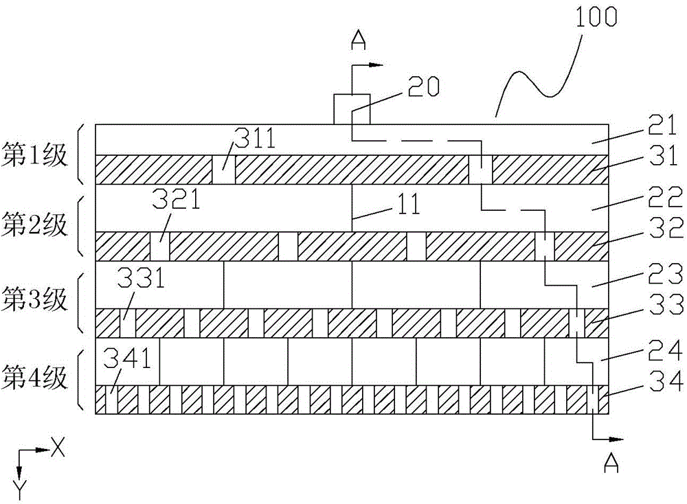
[0070] Figure 3A The schematic diagram of the air intake device provided by the second embodiment of the present invention. see Figure 3A Compared with the above-mentioned first embodiment, the gas inlet device provided in this embodiment differs only in that: in this embodiment, the 1st to N-1 level uniform gas layers transport the reaction gas step by step along the horizontal direction, and the 1st to N-1 The N-level uniform gas layer transports the reaction gas in the vertical direction.
[0071] specifically, Figure 3B It is a sectional view of the air intake device provided by the second embodiment of the present invention. Figure 3C for Figure 3B Sectional view along line A-A. Please also refer to Figure 3B and 3C , for the 1st to N-1 level gas distribution layers in the air intake chamber 100, compared with the 1st to N-1 level gas distribution layers in the above-mentioned first embodiment, the structure of the two is the same, but only The arrangement d...
no. 3 example
[0076] Figure 4A It is a schematic diagram of the air intake device provided by the third embodiment of the present invention. see Figure 4A Compared with the above-mentioned second embodiment, the air intake device provided by this embodiment is only different in that: N=3, and in the third-level gas uniform layer, the number of shunts allocated by each subunit is four, That is, each sub-unit 43 in the third-level gas homogenization layer directly and evenly distributes the branches allocated by all the sub-units in the second-level gas homogenization layer into four branches along the direction perpendicular to the direction of conveying the reaction gas in one-to-one correspondence. .
[0077] specifically, Figure 4B It is a sectional view of the air intake device provided by the third embodiment of the present invention. see Figure 4B , as for the first to second level gas homogenization layers in the air intake chamber 200 , compared with the first to second leve...
PUM
 Abstract
Description
Claims
Application Information
 - R&D
- Intellectual Property
- Life Sciences
- Materials
- Tech Scout
- Unparalleled Data Quality
- Higher Quality Content
- 60% Fewer Hallucinations
Browse by: Latest US Patents, China's latest patents, Technical Efficacy Thesaurus, Application Domain, Technology Topic, Popular Technical Reports.
© 2025 PatSnap. All rights reserved.Legal|Privacy policy|Modern Slavery Act Transparency Statement|Sitemap|About US| Contact US: help@patsnap.com