Braking power generating mechanism based on air compression

A technology of braking power generation and air compression, applied in the direction of brake disc, brake type, electric braking system, etc., it can solve the waste of thermal energy consumption, recover braking energy, and the braking torque of the motor cannot meet the braking force demand of the whole vehicle, etc. problem, to achieve the effect of increasing the energy saving effect

Active Publication Date: 2016-02-17
NANTONG YOUYUAN ART PATTERN DESIGN CO LTD
View PDF6 Cites 5 Cited by
  • Summary
  • Abstract
  • Description
  • Claims
  • Application Information

AI Technical Summary

Problems solved by technology

At this stage, the effectiveness of the braking energy recovery system is insufficient, especially when the braking demand is large, the braking torque generated by the motor cannot meet the braking force demand of the whole vehicle. At this time, mechanical braking is required to intervene and provide additional braking Torque, resulting in waste of heat energy generated by mechanical braking
In addition, due to the limitation of the charging and discharging times of the power battery, frequent braking charging and discharging will also have a certain impact on the service life of the power battery, which will correspondingly reduce the service life of the power battery.
In addition, because the existing braking energy recovery system needs to use the power battery, because the power battery is mostly used in the hybrid system and the pure electric vehicle, and the traditional vehicle cannot use the existing braking energy recovery system to recover the braking energy

Method used


Image

  • Braking power generating mechanism based on air compression
  • Braking power generating mechanism based on air compression
  • Braking power generating mechanism based on air compression

Examples


Embodiment Construction

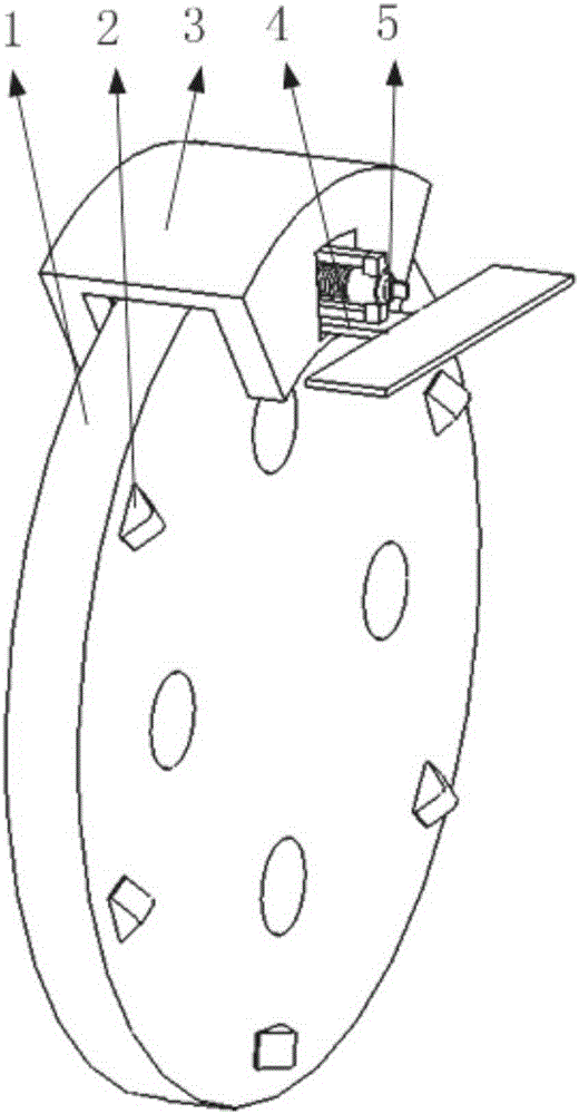
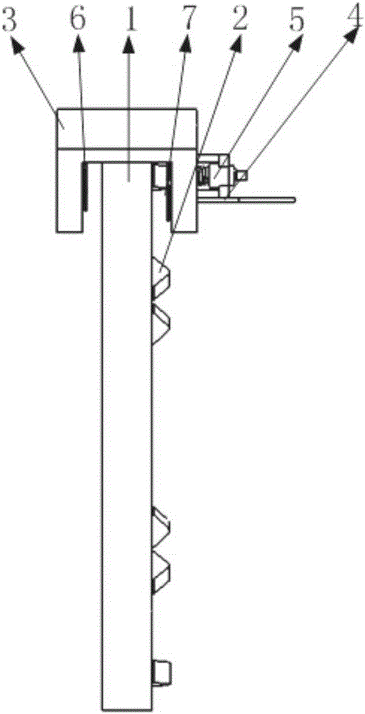
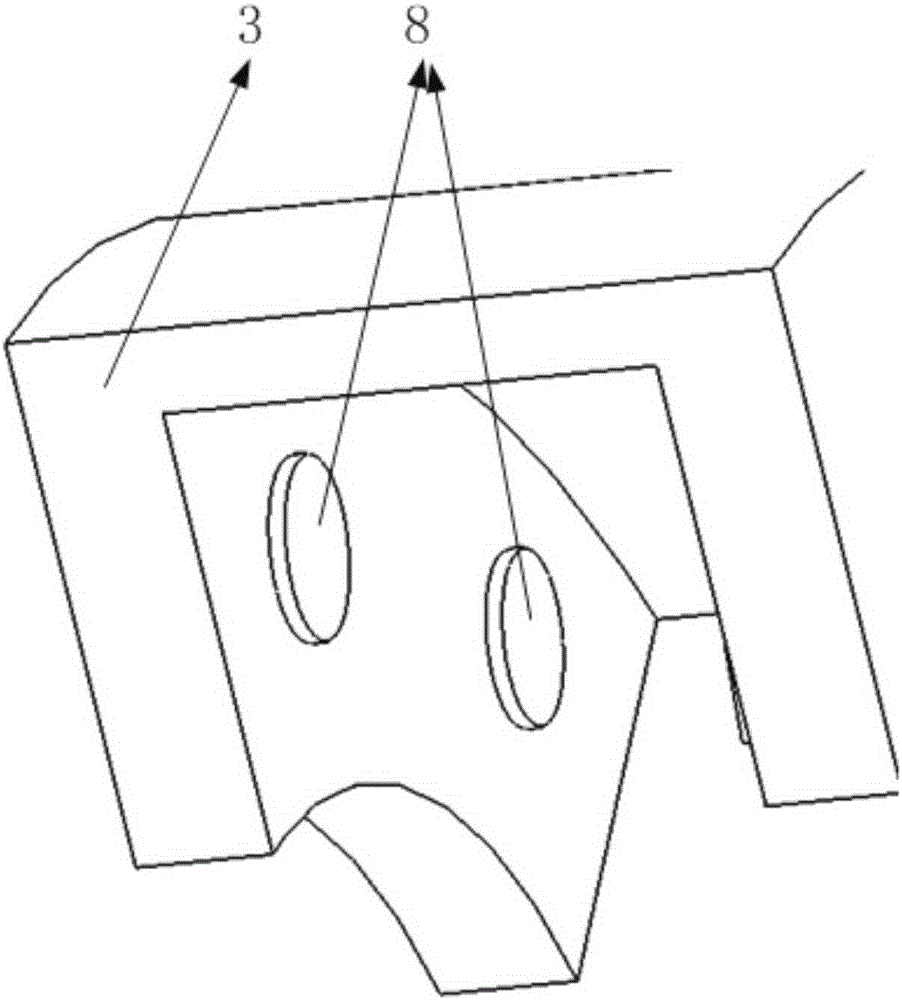
[0043] Such as figure 1 , 2 , 9, 17, 18, 19, 20, it includes brake disc, brake disc protrusion, brake mechanism support, first support plate, braking energy mechanical conversion mechanism, first brake pad bracket, second brake pad Bracket, first brake hydraulic column, second brake hydraulic column, bracket transition piece, second support plate, generator, generator support, air motor, third support plate, first compression cylinder, tie rod fourth support, second Compression cylinder, third compression cylinder, gas tank, gas tank support, tie rod third support, air motor shaft, tie rod second support, compression piston, tie rod first support, tie rod, gas tank air inlet, air tank outlet, Third compression cylinder air outlet, third compression cylinder air inlet, second compression cylinder air outlet, second compression cylinder air inlet, first compression cylinder air outlet, first compression cylinder air inlet, air motor air inlet , Air motor vent, air motor support, ...


PUM


Abstract

The invention belongs to the field of automobile braking energy recycling, and particularly relates to a braking power generating mechanism based on air compression. The braking power generating mechanism comprises a brake disc, brake disc protrusions, a brake mechanism support, a brake energy mechanical conversion mechanism, brake plate supports, hydraulic columns, a power generator, an air motor, compression cylinders, an air tank and pistons. The brake plate supports are arranged on the brake mechanism support. When the brake disc rotates, in the initial stage of the brake process, brake plates are gradually close to the brake disc, an ejector block is in contact matched with the protrusions firstly, the ejector block linearly moves in a reciprocating manner in the direction of a cylinder guide rail, the pistons are driven to reciprocate through cooperation, and accordingly the air motor is driven to drive the power generator to generate power. In the later braking stage, the brake plates start to make contact with the brake disc, larger friction force is generated, and wheels are forcefully braked. By means of cooperation of the ejector block and the protrusions, braking energy is converted into reciprocating movement, the air motor is driven to drive the power generator to generate power accordingly, the brake energy can be effectively utilized, and the energy saving effect of an automobile is improved.

Description

Technical field [0001] The invention belongs to the field of automobile braking energy recovery, and in particular relates to a braking power generation mechanism based on air compression. Background technique [0002] Since the beginning of the 21st century, energy and the environment have increasingly affected human life and social development. Energy-saving and emission-reduction technologies for transportation vehicles are becoming increasingly prominent, vehicle energy recovery technology has received full attention, and braking energy recovery systems have been widely used in electric vehicles and hybrid vehicles. [0003] At present, the basic principle of braking energy recovery for vehicles with a braking energy recovery system is: during the braking process, the electric motor is used to generate electricity and the electric energy is stored in the power battery to realize the recovery and utilization of the braking energy. At this stage, the effectiveness of the braking...

Claims


Application Information

Patent Timeline
Patent Type & Authority Applications(China)
IPC IPC(8): F16D65/12B60L7/10
CPCB60L7/10F16D65/12F16D2065/1316
Inventor 柳超
Owner NANTONG YOUYUAN ART PATTERN DESIGN CO LTD
Why Eureka
Try Eureka