Energy-saving waste liquid recycling device

A waste liquid recovery and recovery tank technology, applied in separation methods, organic chemistry, evaporator accessories, etc., can solve the problems of long heating time, high cost, slow speed, etc., to save operating costs, cooling and evaporation speed, full cooling effect

Inactive Publication Date: 2016-02-24
ZHEJIANG TOP MEDICINE
View PDF8 Cites 0 Cited by
  • Summary
  • Abstract
  • Description
  • Claims
  • Application Information

AI Technical Summary

Problems solved by technology

[0004] However, the heating conduction efficiency in the prior art is not high, and the rate of heat conduction to the center of the methyl isobutyl ketone solution is slow, resulting in long heating time and relatively high cost

Method used


Image

  • Energy-saving waste liquid recycling device

Examples


Embodiment 1

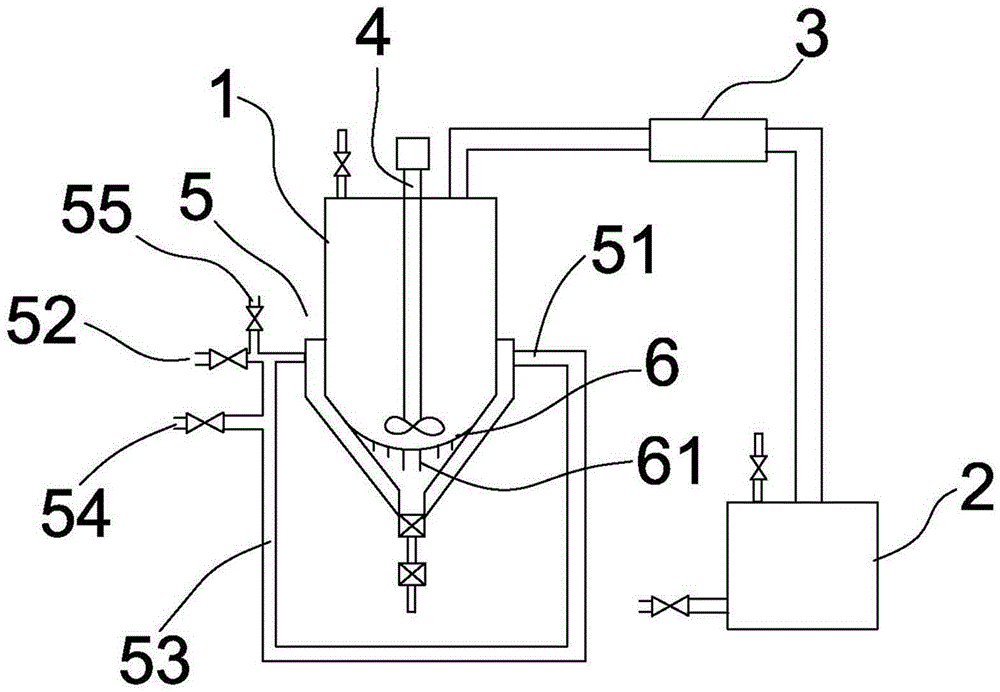
[0027] Embodiment 1: an energy-saving waste liquid recovery device, comprising a separation tank 1 and a recovery tank 2 connected to the separation tank 1, a cooling device 3 is provided between the separation tank 1 and the recovery tank 2, and the The separation tank 1 is provided with a stirring device 4 and a heating device 5, respectively. The heating device 5 is a jacket 51 arranged on the lower part of the outer surface of the separation tank 1. The jacket 51 is provided with a steam inlet 52. A steam circuit 53 is arranged on the jacket 51, and a steam outlet 54 is arranged on the steam circuit 53; a cooling gas inlet 55 is arranged at the steam inlet 52, and the steam inlet 52 and the cooling gas inlet 55 can only be selected from one another. One way to open.

Embodiment 2

[0028] Embodiment 2: an energy-saving waste liquid recovery device, comprising a separation tank 1 and a recovery tank 2 connected to the separation tank 1, a cooling device 3 is provided between the separation tank 1 and the recovery tank 2, and the The separation tank 1 is provided with a stirring device 4 and a heating device 5, respectively. The heating device 5 is a jacket 51 arranged on the lower part of the outer surface of the separation tank 1. The jacket 51 is provided with a steam inlet 52. A steam circuit 53 is arranged on the jacket 51, and a steam outlet 54 is arranged on the steam circuit 53; a cooling gas inlet 55 is arranged at the steam inlet 52, and the steam inlet 52 and the cooling gas inlet 55 can only be selected from one another. One way to open.

[0029] The stirring device 4 in the separation tank 1 is provided with a heat conduction part 6 connected to the inner wall of the separation tank 1. The heat conduction part 6 is a mesh curved downward on th...


PUM

PropertyMeasurementUnit
porosityaaaaaaaaaa

Abstract

The invention relates to a quick waste liquid recycling device and belongs to the technical field of waste liquid recycling. The quick waste liquid recycling device comprises a separation tank and a recycling tank connected with the separation tank. A cooling device is arranged between the separation tank and the recycling tank. A stirring device and a heating device are arranged in and out of the separation tank respectively. The quick waste liquid recycling device is characterized in that a heat conductive part connected with the inner wall of the separation tank is arranged below the stirring device in the separation tank, the heat conductive part is in a screen shape, and holes are formed in the heat conductive part. The waste liquid recycling device is quick to operate and saves time cost.

Description

technical field [0001] The invention relates to the technical field of waste liquid recovery, in particular to an energy-saving waste liquid recovery device. Background technique [0002] In the process of producing dihydrophenylglycine sodium salt, the finished product is obtained by centrifugation and drying. The generated methyl isobutyl ketone after centrifugation contains a small amount of methanol. In order to ensure the performance of methyl isobutyl ketone, it is necessary to Methyl isobutyl ketone is washed and recovered. [0003] In the prior art, sodium chloride solution is used to react with the mixed solution of methyl isobutyl ketone and methanol, then the methanol located in the lower layer of the solution is discharged, and the methyl isobutyl ketone above the solution is evaporated by heating and then condensed and recovered. [0004] However, the heating conduction efficiency in the prior art is not high, and the rate of heat conduction to the center of th...

Claims


Application Information

Patent Timeline
Patent Type & Authority Applications(China)
IPC IPC(8): B01D1/00B01D1/30C07C49/04C07C45/81
Inventor 姚凤鸣谢再法郭锋燕
Owner ZHEJIANG TOP MEDICINE
Why Eureka
Try Eureka