

A Fiber Laser Welding Method for Reducing Welding Spatter
A fiber laser, welding method technology, applied in laser welding equipment, welding/welding/cutting items, welding equipment, etc., to achieve the effects of improving stability, improving welding quality, and reducing welding spatter
- Summary
- Abstract
- Description
- Claims
- Application Information
AI Technical Summary
Problems solved by technology
Method used
Image

Examples
Embodiment 1
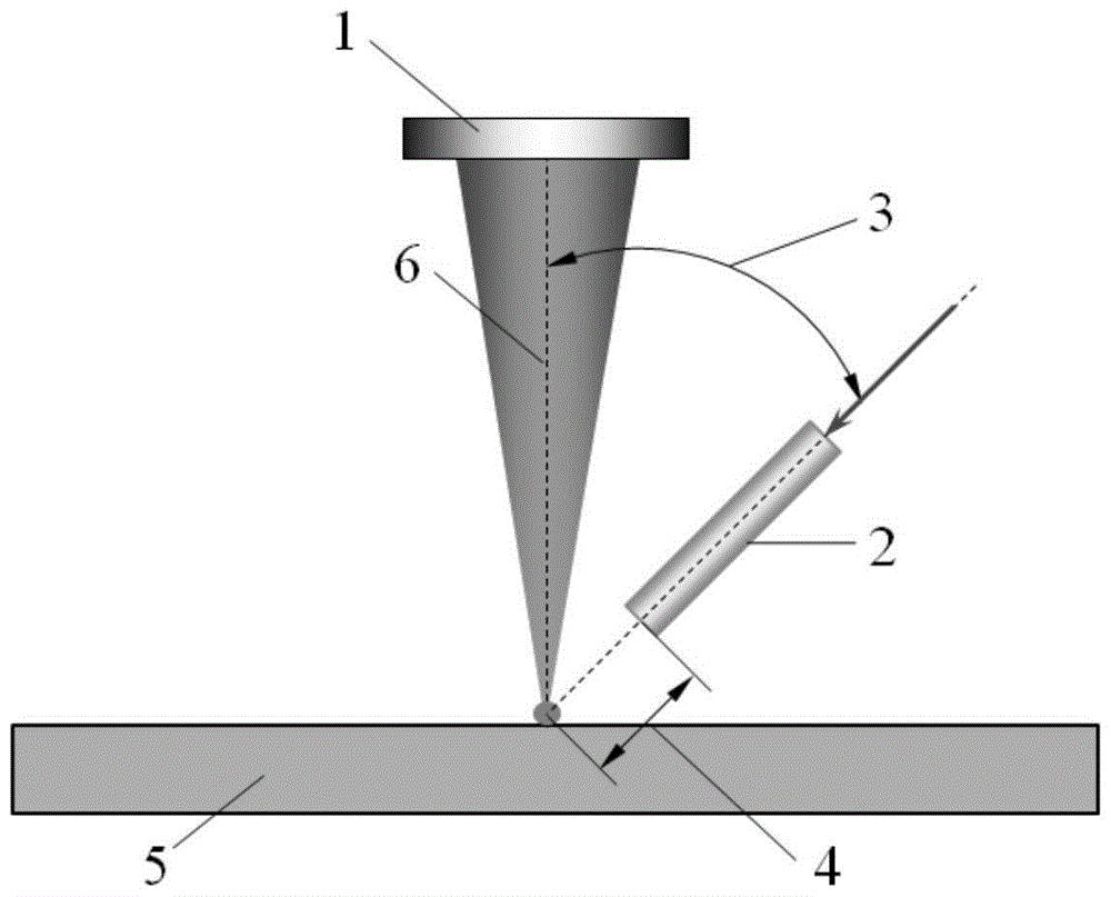
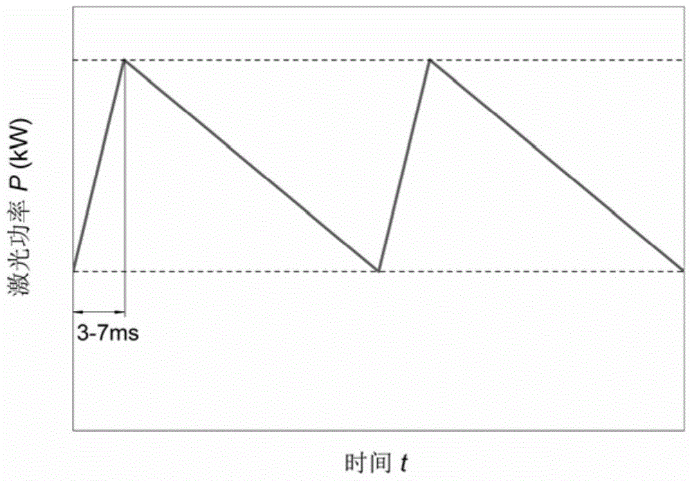
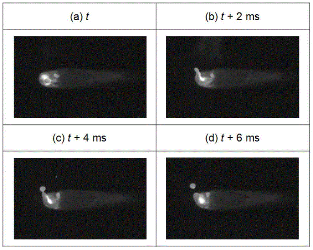
[0041] For high-strength steel with a thickness of 20mm and 600MPa grade, that is, the workpiece 5, the fiber laser welding method of the present invention is adopted, wherein the laser power of the fiber laser 1 is modulated into a triangular wave pulse, the pulse peak power is 7kW, the base value power is 3kW, the pulse frequency is 15-125Hz, and the triangular wave pulse The pulse rise time is 5 ms, the flow rate of the argon shielding gas is 15 L / min, the angle 3 between the shielding gas nozzle and the laser beam axis 6 is 45°, and the distance 4 between the shielding gas nozzle 2 and the workpiece 5 is 15mm, welding speed 1.0m / min. When the pulse frequency is 15-125Hz, the spatter particles attached to the surface of the fiber laser welding seam are less and small (such as Figure 4 Shown), while the optical fiber laser welding method with unmodulated power in the comparison method, the force of the metal vapor eruption in the small hole makes the molten pool at the fron...
Embodiment 2
[0044] For low-carbon steel with a thickness of 15mm, i.e. workpiece 5, the fiber laser welding method of the present invention is adopted, wherein the laser power of laser 1 is modulated into a triangular wave pulse, the pulse peak power is 7kW, the base value power is 3kW, the pulse frequency is 60Hz, and the rising edge of the triangular wave pulse The time is 5ms, the flow rate of the helium shielding gas is 45L / min, the angle 3 between the shielding gas nozzle 2 and the laser beam axis 6 is 40°, and the distance 4 between the shielding gas nozzle 2 and the workpiece 5 is 12mm. The welding speed is 1.0m / min. The weight loss of fiber laser welding with triangular wave pulse modulation is 0.29g, while the fiber laser welding method with unmodulated power of the comparison method has a weight loss of 0.53g. Using triangular wave pulse modulation, fiber laser welding spatter is greatly reduced, and weight loss is significantly reduced.
Embodiment 3
[0046]For 12mm thick 780MPa high-strength steel, that is, workpiece 5, the fiber laser welding method is adopted, in which the laser power of laser 1 is modulated into a triangular wave pulse, the pulse peak power is 5kW, the base value power is 2kW, the pulse frequency is 100Hz, and the rising edge time of the triangular wave pulse is 5ms. The flow rate of the argon shielding gas 2 is 10L / min, the angle 3 between the shielding gas nozzle 2 and the laser beam axis 6 is 45°, the distance 4 between the shielding gas nozzle 2 and the workpiece 5 is 10mm, and the welding speed 0.5m / min. The weight loss of fiber laser welding with triangular wave pulse modulation is 0.42g, while the fiber laser welding method with unmodulated power of the comparison method has a weight loss of 0.65g. Using triangular wave pulse modulation, fiber laser welding spatter is greatly reduced, and weight loss is significantly reduced.
PUM
| Property | Measurement | Unit |
|---|---|---|
| thickness | aaaaa | aaaaa |
Abstract
Description
Claims
Application Information