Solar tube and its processing method

A technology of solar energy and internal tubes, applied in the field of solar tubes and their processing, can solve problems such as high cost, increased saturated steam pressure, and difficult batch processing

Inactive Publication Date: 2019-03-22
北京越洋高科节能技术有限公司
View PDF4 Cites 0 Cited by
  • Summary
  • Abstract
  • Description
  • Claims
  • Application Information

AI Technical Summary

Problems solved by technology

However, this kind of solar tube has the same problem as ordinary solar tubes: when the heat exchange cannot be carried out, the saturated steam pressure is too high due to the continuous backflow of the working fluid and the continuous rise of the temperature inside the tube, and it is easy to explode the tube.
Moreover, its structure is too complex, and batch processing is difficult. Compared with ordinary solar collector tubes, the cost is high and cannot meet market demand.

Method used


Image

  • Solar tube and its processing method
  • Solar tube and its processing method
  • Solar tube and its processing method

Examples


Embodiment 2

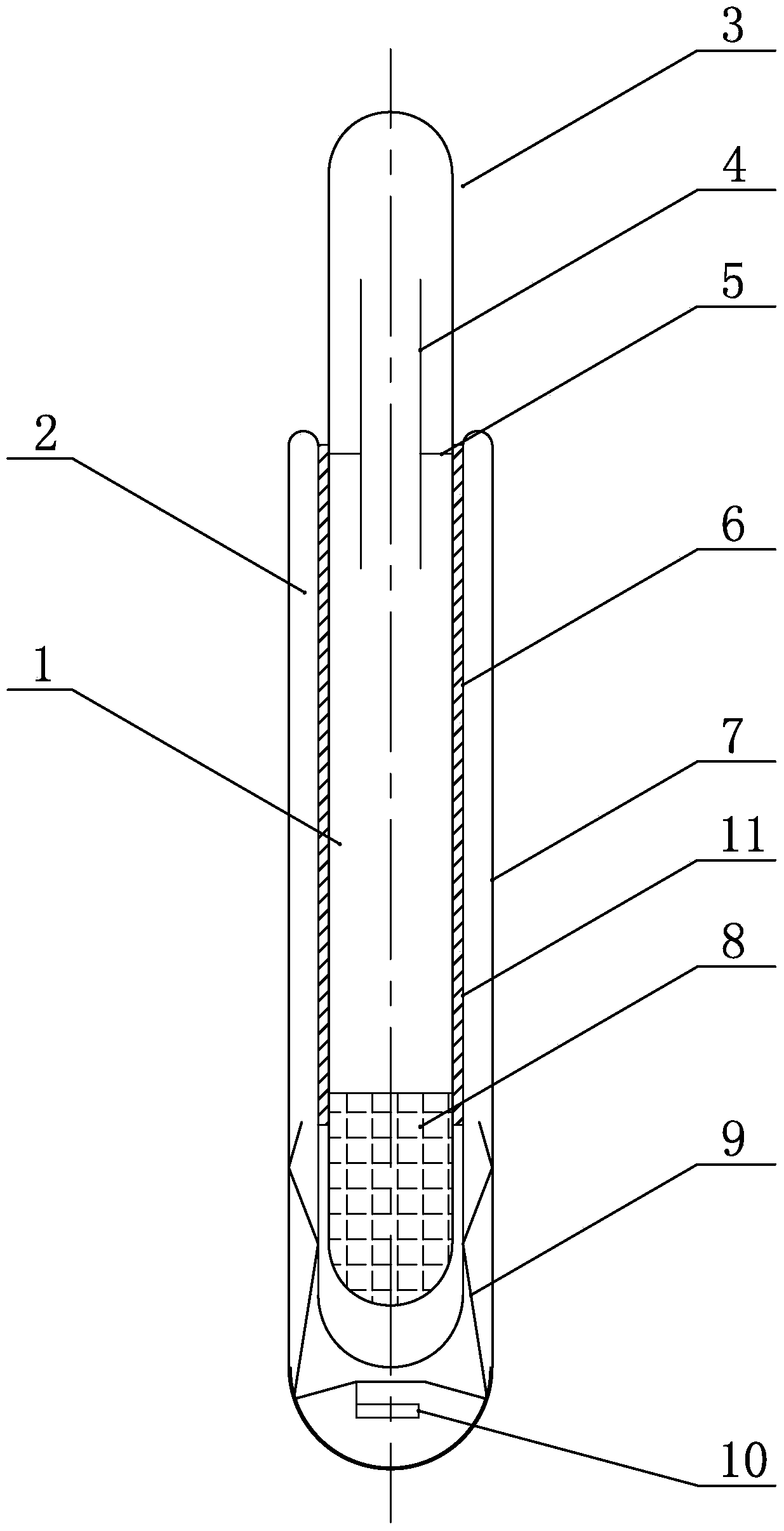
[0035] Example 2, such as figure 2As shown, the difference between this embodiment and Embodiment 1 lies in that: a heat-conducting material 11 is arranged inside the inner tube 6, and the heat-conducting material is selected from heat-conducting adhesive, heat-conducting pad or heat-conducting silicone grease.

Embodiment 3

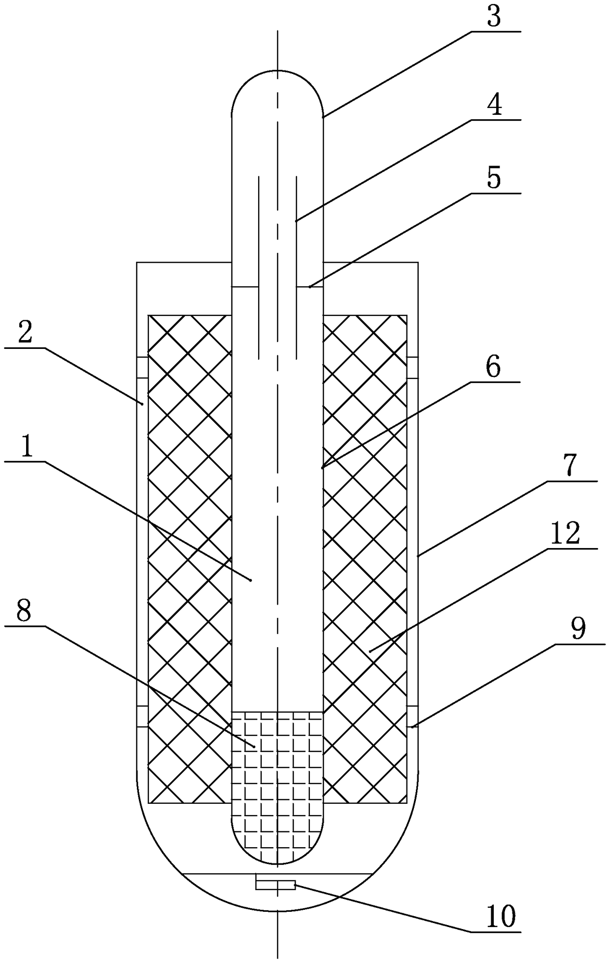
[0036] Example 3, such as image 3 As shown, the difference between this embodiment and Embodiment 1 lies in that: a CPC reflector 12 is arranged in the outer vacuum cavity 2 .


PUM


Abstract

The invention relates to a solar tube and a machining method thereof, in particular to the solar tube capable of achieving the functions of heat collecting and refrigerating and the machining method thereof. The solar tube which is simple in structure, safe in use and low in cost and the machining method thereof are provided. The solar tube comprises an inner tube body and a cover glass tube arranged outside the inner tube body in a sleeving mode. A condensing tube is arranged above the inner tube body. The connector position of the condensing tube, the inner tube body and the cover glass tube is sealed to form an annular sealing opening. An inner vacuum cavity body is formed between the condensing tube and the inner tube body, and an outer vacuum cavity body is formed between the inner tube body and the cover glass tube. An annular clapboard arranged horizontally is fixed to the inner wall of the inner vacuum cavity body and is fixed to the upper portion of the inner vacuum cavity body. A flow resisting tube is installed on the annular clapboard. The central axial line of the flow resisting tube is parallel to that of the inner tube body. A working medium is arranged at the bottom of the inner vacuum cavity body. The external surface of the inner tube body is coated with a selective absorbing coating. A bracket is arranged inside the outer vacuum cavity body. A getter is placed on the bracket.

Description

technical field [0001] The invention relates to a solar tube and a processing method thereof, in particular to a solar tube capable of realizing heat collection and cooling functions and a processing method thereof. Background technique [0002] At present, the all-glass vacuum solar heat collector is mainly used for solar heat collection, and the technology is very mature. It is widely used in low-temperature solar heat utilization products, forming a market scale with an annual output value of nearly 100 billion. But using the same solar tube to make full use of solar energy and realize the dual functions of heat collection and cooling, there are still few researches on technologies and products. [0003] The Chinese invention patent with the publication number CN 1393668A proposes a solar tube that can realize heat collection and refrigeration, including an adsorption / heat collector and a condensation / evaporator. The adsorption / heat collector is filled with adsorbent, and...

Claims


Application Information

Patent Timeline
Patent Type & Authority Patents(China)
IPC IPC(8): F25B29/00F25B27/00
CPCF25B27/002F25B29/00
Inventor 韩成明邓国张克雨
Owner 北京越洋高科节能技术有限公司
Why Eureka
Try Eureka