Backlight module and display device
A backlight module and light source technology, applied in the optical field, can solve the problems of poor brightness uniformity and chromaticity uniformity, and achieve the effect of improving brightness and chromaticity uniformity and reducing leakage
- Summary
- Abstract
- Description
- Claims
- Application Information
AI Technical Summary
Problems solved by technology
Method used
Image

Examples
Embodiment 1
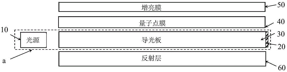
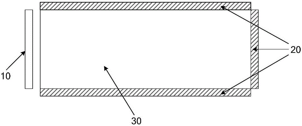
[0039] The backlight module provided in this embodiment includes a blue light source, a light guide plate, and a reflective layer. The light guide plate has a light incident surface, a first light exit surface, three light leakage surfaces, and a second light exit surface parallel to the first light exit surface. The light incident surface of the light plate is arranged correspondingly, and the reflective layer is arranged correspondingly to the second light outlet surface of the light guide plate. The backlight module also includes a light conversion layer arranged on a light leakage surface. The material is CdSe / ZnS core-shell quantum dots, the base material of the light conversion layer is polyacrylate, the particle diameter of the quantum dots is 10nm, the weight percentage of the quantum dots in the light conversion layer is 8%, and the thickness of the light conversion layer is 200μ0, And the thickness of the light guide plate is 4mm.
Embodiment 2
[0041] The backlight module provided by this embodiment has the following differences from Embodiment 1, and the others are the same as Embodiment 1:
[0042] The light conversion layer is arranged on each light leakage surface, the light conversion material in the light conversion layer is YAG phosphor powder, the base material of the light conversion layer is silica gel, the weight percentage of the phosphor powder in the light conversion layer is 8%, the light conversion layer The thickness is 200μ0, and the thickness of the light guide plate is 4mm.
Embodiment 3
[0044] The backlight module provided by this embodiment has the following differences from Embodiment 1, and the others are the same as Embodiment 1:
[0045] The light conversion layer is arranged on each light leakage surface, the particle size of the CdSe / ZnS core-shell quantum dots is 10nm, the weight percentage of the quantum dots in the light conversion layer is 15%, the thickness of the light conversion layer is 100%, and the light guide plate The thickness is 1mm.
PUM
| Property | Measurement | Unit |
|---|---|---|
| Thickness | aaaaa | aaaaa |
| Thickness | aaaaa | aaaaa |
| Particle size | aaaaa | aaaaa |
Abstract
Description
Claims
Application Information
PatSnap Eureka turns technology decisions into work you can execute. Powered by our Innovation Knowledge Graph, it runs expert workflows across engineering, life sciences, materials and intellectual property. Get your review-ready output in minutes.


