
An optical fiber smoke sensor

A technology of smoke sensor and optical fiber, which is applied in the field of automatic smoke alarm equipment, can solve the problems of high detector structure, unsafe, unsuitable installation, etc., and achieve the effect of reducing interference

Inactive Publication Date: 2017-08-25
ANHUI ZHONG XI COMM TECH CO LTD
View PDF4 Cites 0 Cited by
  • Summary
  • Abstract
  • Description
  • Claims
  • Application Information

AI Technical Summary

Problems solved by technology

[0003] The problems of photoelectric smoke detectors are: ①Because of the electric signal, it is not suitable for installation in places with flammable and explosive and high electromagnetic radiation intensity, and there are certain safety hazards ②Electronic components are easy to age, and false alarms are easy to occur after aging Even failure ③The detector structure is complex, and the maintenance cost is high in the later period ④Because it cannot resist ambient light interference, the ambient light is blocked by the complex probe design, but it makes it difficult to detect smoke, it is difficult to remove dust in the later stage, and the sensitivity is not high, etc. defect
[0004] The problems of ion smoke detectors are: ①Because of the electrical signal, it is not suitable for installation in places with flammable, explosive and high electromagnetic radiation intensity, and there are certain safety hazards ②Electronic components are easy to age, and false alarms are easy to occur after aging Even failure ③ complex structure, large volume, inconvenient installation, high production and maintenance costs ④ radioactive elements are used as ion sources, which is very unsafe
[0005] The problems of infrared beam (laser) line smoke detectors are: ①Because of the electrical signal, it is not suitable for installation in places with high electromagnetic radiation intensity, which is inflammable and explosive, and there are certain safety hazards; ②Electronic components are easy to age, After aging, it is easy to produce false alarms or even malfunction ③Easily interfered by infrared light and ultraviolet light, the detection beam is easily blocked to produce high false alarms ④The detector structure is complex and the maintenance cost is high
[0006] The above shortcomings of the existing technology make it no longer suitable for the needs of automatic fire alarms. A new type of smoke sensing technology is urgently needed, such as optical fiber smoke sensing. At the same time, in order to give full play to the advantages of optical fiber smoke sensing, it must be equipped with specially designed optical fiber smoke sensor

Method used


Image

  • An optical fiber smoke sensor
  • An optical fiber smoke sensor
  • An optical fiber smoke sensor

Examples


Embodiment 1

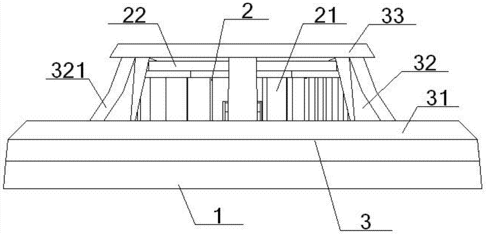
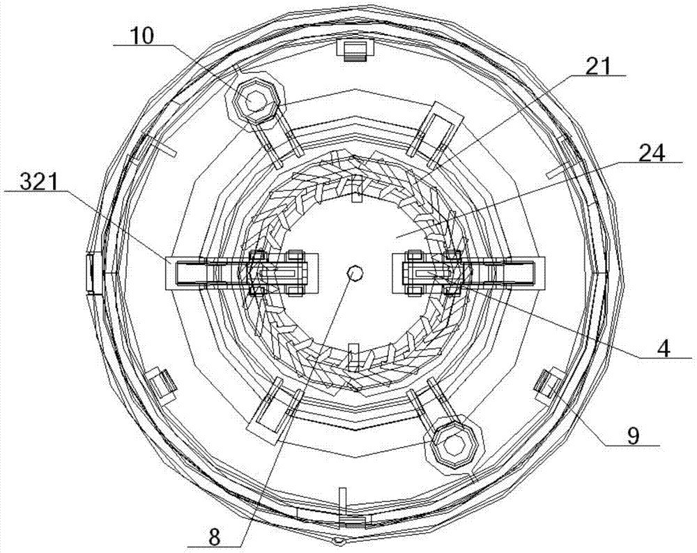
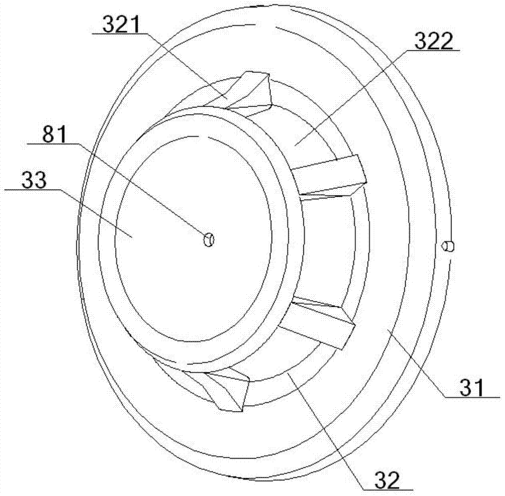
[0063] see figure 1 – Figure 12 , an optical fiber smoke sensor, comprising a bottom case 1, a smoke chamber 2, a mask 3 and an optical fiber fixing device 4, the mask 3 is a concave structure, including a top cover part 31, a middle cover part 32 and a bottom cover part 33, the The periphery of the bottom cover part 33 is connected with the middle part of the top cover part 31 through the middle cover part 32, and the periphery of the top cover part 31 is connected with the periphery of the bottom shell 1, and the bottom shell 1 is provided with a fixing hole 10, and the bottom shell 1 The middle part of the front is connected with the smoke chamber 2, the outside of the smoke chamber 2 is covered in the mask 3, and the inside of the smoke chamber 2 is provided with an optical fiber fixing device 4;

[0064] The optical fiber fixing device 4 includes a left-right symmetrical optical fiber inlet 41 and an optical fiber outlet 42 with the same structure, and the symmetrical p...

Embodiment 2

[0066] Basic content is the same as embodiment 1, the difference is:

[0067] The two sides of the front wide plate 61 are respectively connected with a side plate 63 , and the side plate cavity 64 formed between the two side plates 63 is inlaid with the fiber receiving platform 51 inside. Described side plate 63 comprises front long side plate 631, medium and short side plate 632 and rear long side plate 633, and middle and short side plate 632 is shorter than front long side plate 631, rear long side plate 633, and front long side plate 631, rear long side plate 633 One end of the long side plate 633 is connected to the side of the front wide plate 61 , and the other ends of the front long side plate 631 and the rear long side plate 633 are engaged with the side plate hole 65 opened on the front of the bottom shell 1 .

Embodiment 3

[0069] Basic content is the same as embodiment 1, the difference is:

[0070] The smoke chamber 2 includes a smoke inlet portion 21 and a circular chassis portion 22. The smoke inlet portion 21 includes a plurality of smoke inlet pieces 23 uniformly distributed in the same circle along the chassis portion 22, and the smoke inlet pieces 23 are surrounded by a The smoke gathering area 24 is circular, and a smoke inlet passage 25 is formed between adjacent smoke inlet pieces 23; two smoke chamber gaps 26 are opened on the smoke inlet portion 21, and each smoke chamber gap 26 is located on the other side. One fiber-supporting platform 51 inside is correspondingly engaged, and the two smoke chamber gaps 26 are symmetrically arranged with the center of the chassis portion 22 as a symmetrical point. The shape of the smoke-introducing sheet 23 is herringbone, letter-shaped, T-shaped or splayed. The smoke inlet part 21 also includes a pair of fixed feet 27, which are symmetrically arr...


PUM


Abstract

The invention relates to a fiber smoke sensor which comprises a bottom casing, a smoke chamber and a surface cover, wherein the middle portion of the bottom casing is connected with the smoke chamber, the smoke chamber is covered in the surface cover, the smoke chamber is internally provided with a fiber inlet portion and a fiber outlet portion in left and right symmetry and structural consistency, a fiber bearing groove and an interboard gap clamped between a fiber bearing pedestal and a fiber pressing top board in the fiber inlet / output portion are communicated with a fiber through groove, a smoke input portion in the smoke chamber comprises smoke input sheets which are arranged uniformly in the same circle along a bottom disk portion, a smoke input channel is formed between the adjacent smoke input sheets, the smoke input portion is also provided with two gaps of the smoke chamber so that the fiber bearing pedestal can be clamped, and the surface cover and the smoke chamber are provided with light guide holes into which light guide columns can be inserted cooperatively. According to the invention, alarm can be raise automatically when fibers sense smoke, the defects caused by electric signals, electronic components and an ion source in the prior art are avoided, interference by environmental light can be avoided, the smoke gathering and insect prevention effects are good, the sensitivity is higher, and the manufacture and use cost is lower.

Description

technical field [0001] The invention relates to an automatic smoke alarm device, in particular to an optical fiber smoke sensor, which is specifically suitable for avoiding the interference of ambient light, enhancing the effect of gathering smoke and preventing insects, and improving the sensitivity on the basis of applying an automatic smoke alarm for optical fiber sensing, and Reduce manufacturing and use costs. Background technique [0002] At present, the smoke detectors used for automatic fire alarm at home and abroad are all photoelectric, ion-type smoke detectors, infrared beam (laser) linear smoke detectors, etc. [0003] The problems of photoelectric smoke detectors are: ①Because of the electric signal, it is not suitable for installation in places with flammable and explosive and high electromagnetic radiation intensity, and there are certain safety hazards ②Electronic components are easy to age, and false alarms are easy to occur after aging Even failure ③The de...

Claims


Application Information

Patent Timeline
Patent Type & Authority Patents(China)
IPC IPC(8): G08B17/103
CPCG08B17/103
Inventor 张森
Owner ANHUI ZHONG XI COMM TECH CO LTD
Learn More