Superconducting magnet comprising ferromagnetic rings

A technology of superconducting magnets and ferromagnetic rings, which is applied to superconducting magnets/coils, magnetic objects, electrical components, etc., can solve the problems of increasing ferromagnetic loss, excessive wire loss, and increasing the volume and weight of superconducting magnets. Achieve the effect of reducing the difficulty of winding and processing, avoiding the rapid quenching of the wire, and reducing the hidden danger of quenching.

Active Publication Date: 2016-02-24
SICHUAN NORMAL UNIVERSITY
View PDF5 Cites 2 Cited by
  • Summary
  • Abstract
  • Description
  • Claims
  • Application Information

AI Technical Summary

Problems solved by technology

However, this solution requires a ring-shaped ferromagnetic sheet with a large thickness and width. On the one hand, it increases a large amount of ferromagnetic loss, and at the same time increases the volume and weight of the entire superconducting magnet. Difficulty with actual installation and operation inside the container
In addition, the ring-shaped ferromagnetic sheet has a poor attenuation effect on the vertical magnetic field component around the inner coil wire near the winding bobbin, which may easily cause the critical current density of the inner coil wire to be too low, thereby causing the wire loss to exceed fast and local Safety hazards such as overheating

Method used


Image

  • Superconducting magnet comprising ferromagnetic rings
  • Superconducting magnet comprising ferromagnetic rings
  • Superconducting magnet comprising ferromagnetic rings

Examples


Embodiment Construction

[0027] The present invention will be further described in detail below in combination with specific embodiments. However, it should not be understood that the scope of the above subject matter of the present invention is limited to the following embodiments, and all technologies realized based on the content of the present invention belong to the scope of the present invention.

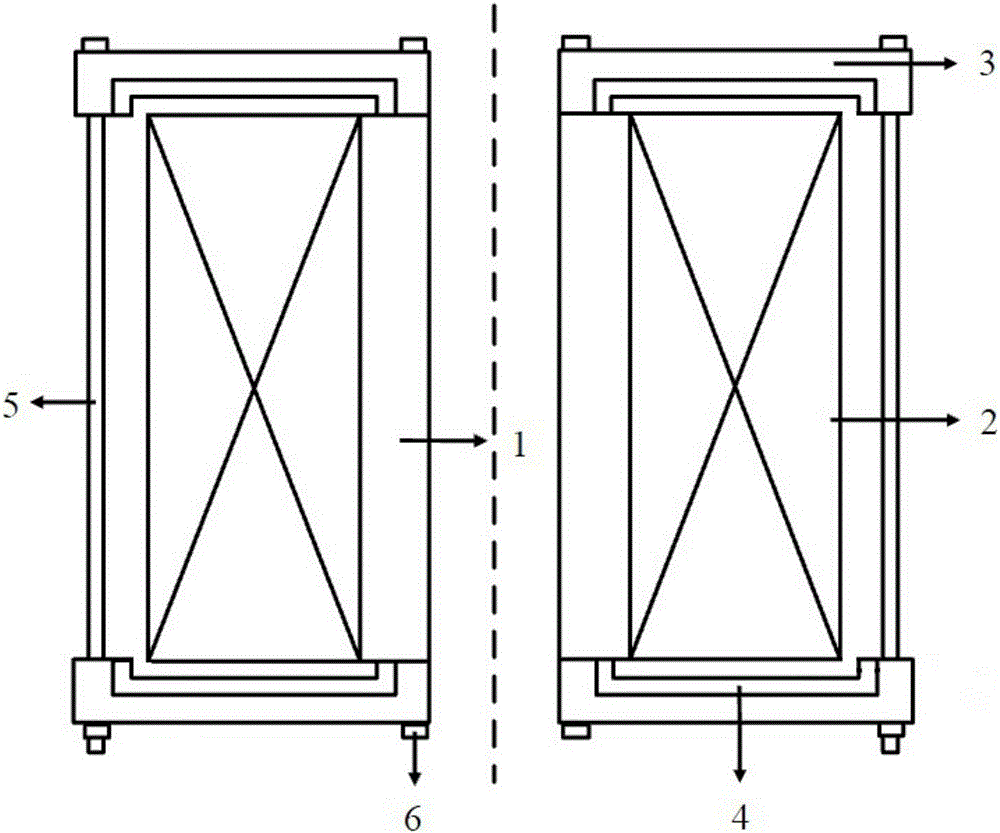
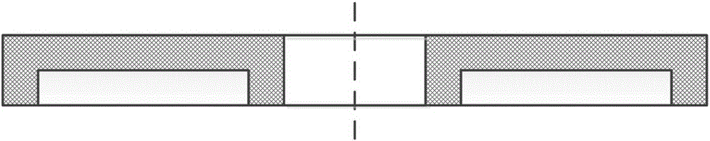
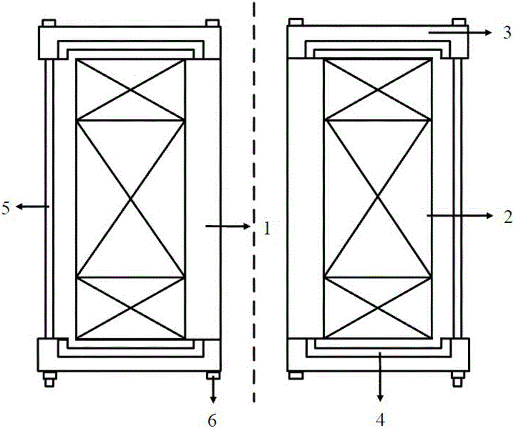
[0028] combine figure 1 with figure 2 Schematic diagram of the structure of the present invention and a sectional view of the ferromagnetic ring of the present invention shown respectively; wherein, the superconducting magnet containing the ferromagnetic ring of the present invention includes a non-magnetic cylindrical skeleton 1, a superconducting solenoid coil 2 and Two annular cover plates 3, and the superconducting solenoid coil 2 is wound on the non-magnetic cylindrical frame 1, and an annular cover plate 3 is provided at both ends of the non-magnetic cylindrical frame 1 to cover the supercondu...


PUM


Abstract

The invention discloses a superconducting magnet comprising ferromagnetic rings. The superconducting magnet comprises a non-magnetic cylindrical framework, a superconducting solenoid coil and two annular cover plates, wherein one ferromagnetic ring is embedded on the surface, close to the superconducting solenoid coil, of each annular cover plate and is coaxial with the corresponding annular cover plate; one annular groove with a certain groove depth is formed in the surface, close to the superconducting solenoid coil, of each ferromagnetic ring, accordingly, an inner annular boss and an outer annular boss are formed on the inner edge and the outer edge of each ferromagnetic ring respectively, and the radial width between the inner annular boss and the outer annular boss is equal to the groove depth of each annular groove; the end surface of the superconducting solenoid coil is parallel to the bottom surface of the annular groove at the interval being the groove depth of each annular groove, and the numerical value of the interval between the inner edge of the end surface of the superconducting solenoid coil and the inner annular boss and the numerical value of the interval between the outer edge of the end surface of the superconducting solenoid coil and the outer annular boss are both equal to the groove depth of each annular groove. The critical current of the superconducting magnet is increased by attenuating the vertical magnetic-field component.

Description

technical field [0001] The invention relates to the technical field of superconducting magnets, in particular to a superconducting magnet containing a ferromagnetic ring. Background technique [0002] Compared with conventional copper and aluminum conductive wires, superconducting wires have very high critical current density and nearly zero resistivity. In recent years, superconducting magnets wound by superconducting wires have been widely used in the fields of electric power and energy, such as superconducting magnetic energy storage coils, superconducting transformer windings, superconducting reactor windings, superconducting generator windings, etc. [0003] Superconducting magnets often adopt a solenoid air-core coil structure to obtain higher inductance and energy storage density. However, in this solenoidal air-core coil structure, the main component of the background magnetic field where the axial coil layers at both ends of the magnet are located is the vertical m...

Claims


Application Information

Patent Timeline
IPC IPC(8): H01F6/00H01F6/06
CPCH01F6/00H01F6/06
Inventor 陈孝元
Owner SICHUAN NORMAL UNIVERSITY
Why Eureka
Try Eureka