Conductor line, current collector, and conductor line system

A technology for sliding wires and current collectors, which is applied in the direction of current collectors, current collectors, power collectors, etc., to achieve the effects of material saving, compact structure, and simplified manufacturing and installation

Active Publication Date: 2016-02-24
CONDUCTIX WAMPFLER
View PDF12 Cites 2 Cited by
  • Summary
  • Abstract
  • Description
  • Claims
  • Application Information

AI Technical Summary

Problems solved by technology

However this leads to the fact that moisture and dirt can more easily accumulate on the lower opening gap of the slotted waveguide

Method used


Image

  • Conductor line, current collector, and conductor line system
  • Conductor line, current collector, and conductor line system
  • Conductor line, current collector, and conductor line system

Examples


Embodiment Construction

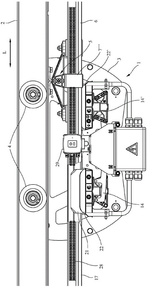
[0034] figure 1 A side plan view of a portion of a conductor line system 1 according to the invention is shown, which has a substantially double U-shaped rail 2 . The current collectors 3 of electrical loads (not shown) are movable on the rail 2 in the longitudinal direction L with impellers 4 . The current collector 3 is used to power an electrical load movable along the track 2, such as a container crane.

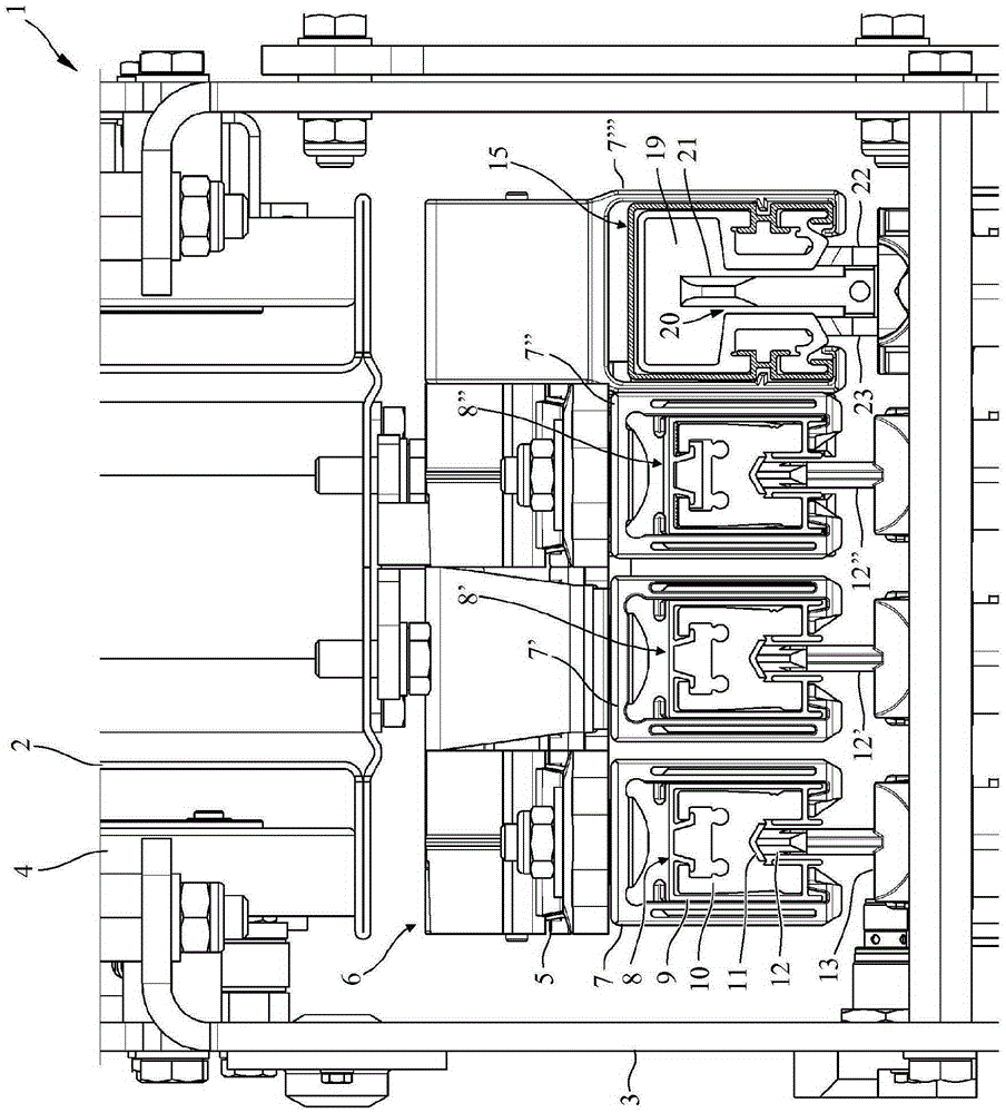
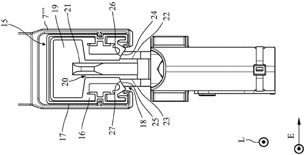
[0035] On the underside of the rail 2 , a conductor conductor 6 according to the invention is mounted suspended downward by means of conductor conductor holders 5 arranged at a distance from one another in the longitudinal direction L of the rail 2 . Sliding wire 6 is here Figures 2 to 5 Three conductor bundle holding structures 7, 7' and 7" arranged next to each other for holding elongated phase conductor bundles 8, 8' and 8" are clearly recognizable. Since the phase conductor bundles 8' and 8" are constructed identically to the phase conductor bundle 8, the descript...


PUM


Abstract

The invention relates to a conductor line (6) for supplying at least one electric load which can be moved on the conductor line in the longitudinal direction (L) of the conductor line, comprising at least one conductor strand (15; 30; 38; 45) which runs in the longitudinal direction (L) and which comprises an electrically conductive profiled conductor section (16; 31; 39; 46) for contacting a sliding contact (22; 23; 33; 43; 56) of the load and at least one signal transmission device (19; 35; 40; 47) which runs in the longitudinal direction (L). The invention also relates to a current collector (3) for the load with at least one sliding contact (22; 23; 33; 43; 56) for contacting the profiled conductor section (16; 31; 39; 46) of the conductor strand (15; 30; 38; 45) of the conductor line (6) and with at least one antenna (21; 37; 44; 49) for transmitting data to a conductor line (6) signal transmission device (19; 35; 40; 47), which moves in the longitudinal direction (L). The invention also relates to a conductor line system. The aim of the invention is to allow a compact and material-saving design as well as a good fault-tolerant transmission. This is achieved by a conductor line (6) in which the signal transmission device (19; 35; 40; 47) and the profiled conductor section (16; 31; 39; 46) are designed as one component, by a current collector (3) in which the sliding contact (22; 23; 33; 43; 56) and the antenna (21; 37; 24; 49) are designed as one component, and by a conductor line system comprising such a conductor line (6) and such a current collector (3).

Description

technical field [0001] The invention relates to a conductor / contact wire according to the preamble of claim 1 , a current collector according to the preamble of claim 12 and a conductor conductor system according to the preamble of claim 24 . Background technique [0002] In known trolley wire systems, a movable electrical load moves along the trolley wire. To supply the load, the load is equipped with a current collector, the sliding contacts of which engage in a conductor bundle which is guided along the contact wire. The load can be, for example, a conveyor hook of a trolley rail, a cable trolley movable on a rail or a so-called E-RTG container crane, which is equipped with an electric travel drive powered by trolley wires. [0003] In order to be able to transmit data, for example control data, to the load, in the known trolley line systems a so-called slotted waveguide / slotted hollow conductor or leaky waveguide is guided parallel to the conductor bundle of the trolley...

Claims


Application Information

Patent Timeline
Patent Type & Authority Applications(China)
IPC IPC(8): H01R41/00H01P3/123H01Q1/22
CPCH01P3/123H01Q1/22H01R41/00B60L5/40B60M1/34H01B5/08H01P3/12
Inventor M·埃克尔B·迈尔
Owner CONDUCTIX WAMPFLER
Why Eureka
Try Eureka