Rib constraint thin-walled steel pipe concrete structure

A technology for concrete structures and thin-walled steel pipes, which is applied to bridge parts, bridge construction, columns, etc., can solve the problems of easy local buckling and low confinement efficiency of core concrete, and achieve the effect of convenient structural construction.

Active Publication Date: 2016-03-02
NANJING FORESTRY UNIV
View PDF2 Cites 4 Cited by
  • Summary
  • Abstract
  • Description
  • Claims
  • Application Information

AI Technical Summary

Problems solved by technology

[0005] The purpose of the present invention is to provide a rib-constrained thin-walled concrete-filled steel tube structure, which solves the problem that the steel tubes in ordinary concrete-filled steel tube structures are not only subjected to vertical axial compression loads, but also are subjected to circumferential tension caused by concrete expansion, resulting in low efficiency of restraining the core concrete. , the technical defect of easy local buckling, this structure not only has the advantages of ordinary steel pipe concrete, but also significantly improves the restraint effect of steel, and is suitable for vertical load-bearing components of various bridges and buildings

Method used


Image

  • Rib constraint thin-walled steel pipe concrete structure
  • Rib constraint thin-walled steel pipe concrete structure
  • Rib constraint thin-walled steel pipe concrete structure

Examples


Embodiment Construction

[0020] In order to have a clearer understanding of the technical features, objectives and effects of the present invention, specific embodiments of the present invention will now be described with reference to the accompanying drawings.

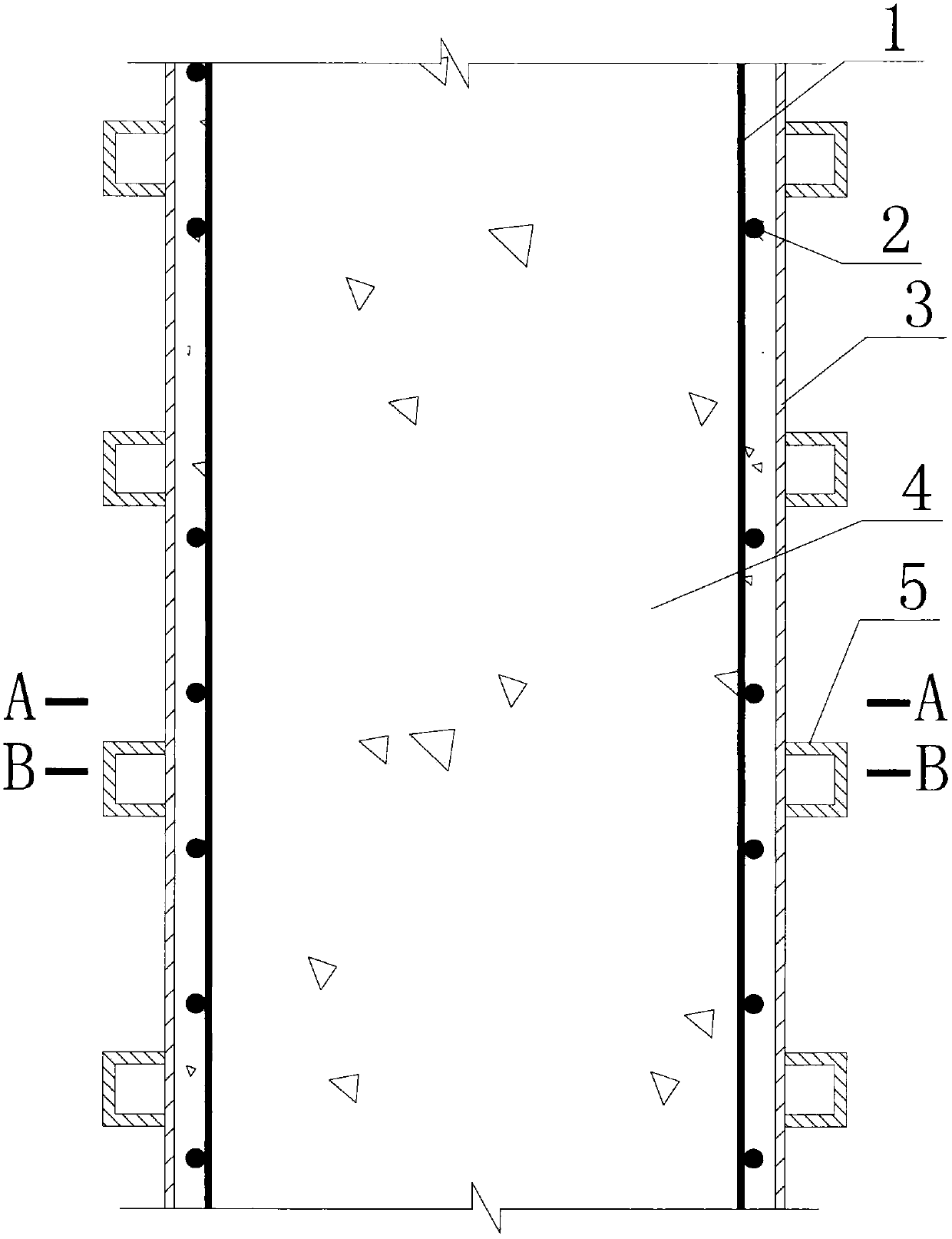
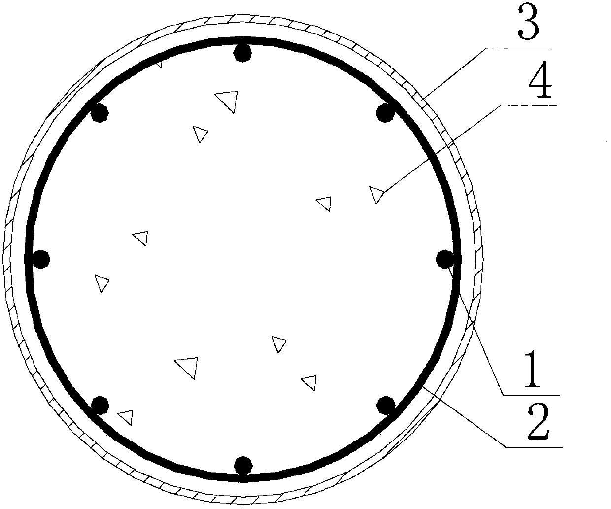
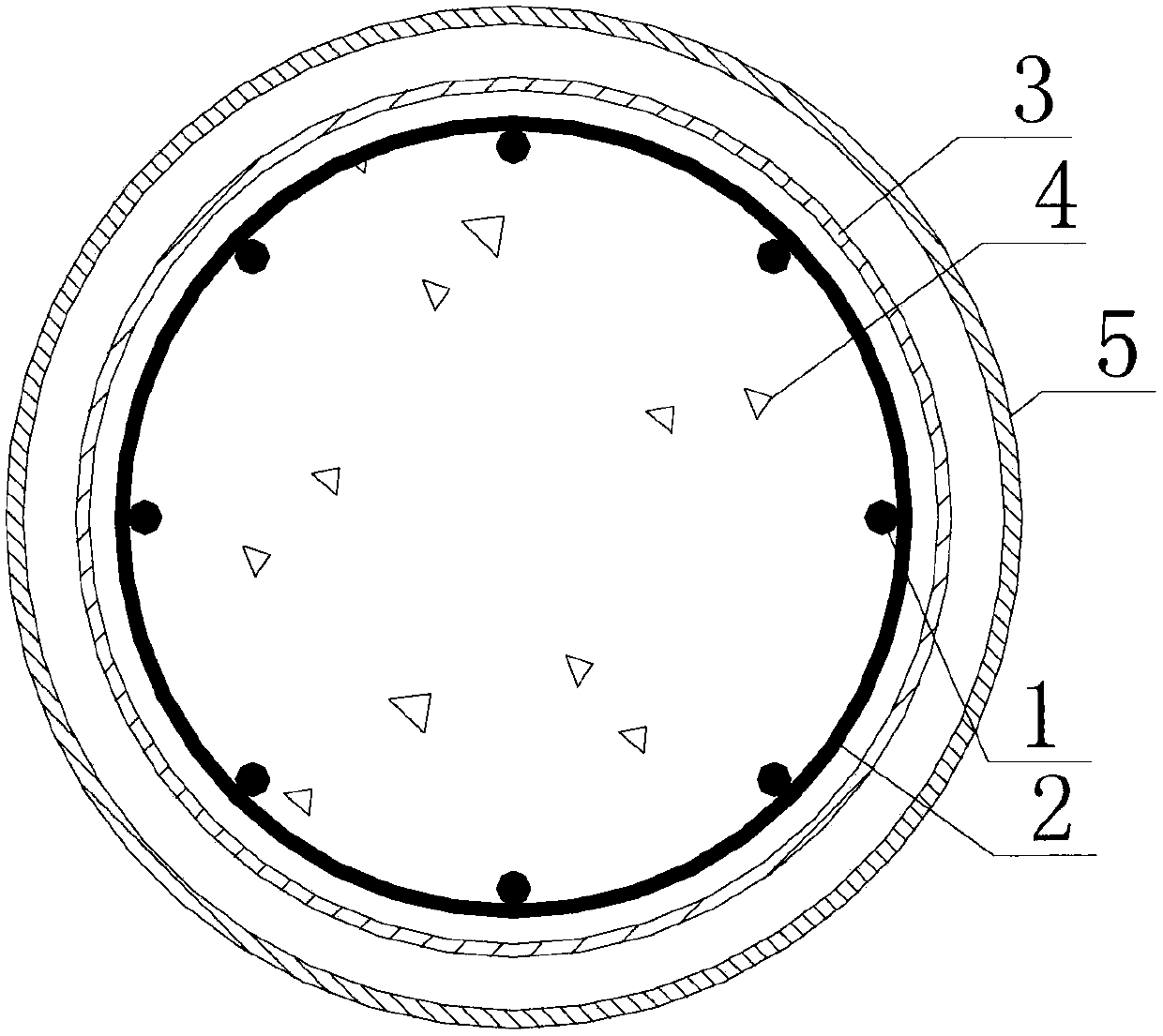
[0021] Such as Figure 1-Figure 5 As shown, the present invention proposes a rib-constrained thin-walled concrete-filled steel tube structure, which is composed of longitudinal reinforcement 1, stirrup 2, thin-walled steel pipe 3, core concrete 4, and steel rib 5, characterized by longitudinal reinforcement 1, stirrup 2 Bundled or welded to form a steel frame, the core concrete 4 wraps the steel frame and fills it inside the thin-walled steel pipe 3. The ratio of the outer diameter or side length to the thickness of the thin-walled steel pipe 3 is greater than or equal to 200, and the vertical spacing of the thin-walled steel pipe 3 Two or more steel ribs 5 are arranged. The steel ribs 5 are connected in a circle along the cross section of the t...


PUM


Abstract

A rib constraint thin-walled steel pipe concrete structure is composed of longitudinal ribs (1), stirrups (2), a thin-walled steel pipe (3), core concrete (4) and steel ribs (5) and is characterized in that the longitudinal ribs (1) and the stirrups (2) are strapped or welded to form a rebar framework which is wrapped by the core concrete (4), the thin-walled steel pipe (3) is filled with the core concrete (4), the ratio of the outer diameter or the edge length of the thin-walled steel pipe (3) to the thickness is larger than or equal to 200, two or more steel ribs (5) are vertically arranged on the thin-walled steel pipe (3) at intervals, the steel ribs (5) are connected in a closed mode annularly along the cross section of the thin-walled steel pipe (3) by a circle, the steel ribs (5) and the outer wall of the thin-walled steel pipe (3) are connected into a whole, and the arrangement interval of the steel ribs (5) is not larger than the outer diameter or the edge length of the thin-walled steel pipe (3). According to the structure, blocking is changed into dredging, the area of the portion, capable of directly bearing vertical loads, of the steel pipe is reduced, the acting efficiency of steel materials is improved, and the rib constraint thin-walled steel pipe concrete structure is suitable for vertical load bearing components of various bridges and buildings.

Description

Technical field [0001] The invention relates to a rib-constrained thin-walled steel tube concrete structure, which is applied to vertical members of various bridges and buildings, and belongs to the field of civil engineering. Background technique [0002] As we all know, concrete has high compressive strength and poor deformability. Steel has strong tensile strength and good elasticity, but it is easy to lose stability when it is compressed and lose its axial compressive capacity. Concrete-filled steel tube refers to a composite structure formed by filling steel tubes with concrete. It can combine the advantages of both concrete and steel tubes. On the one hand, the steel tube forms lateral constraints on the concrete, and the compressive performance of the concrete can be significantly improved. On the one hand, due to the presence of concrete, the formation of lateral support to the steel pipe can prevent or delay the instability of the steel pipe. The concrete-filled steel t...

Claims


Application Information

Patent Timeline
Patent Type & Authority Applications(China)
IPC IPC(8): E04C3/34E01D19/02
CPCE01D19/02E04C3/34
Inventor 魏洋端茂军李国芬
Owner NANJING FORESTRY UNIV
Why Eureka
Try Eureka