Energy recycling control method for PTA device

An energy recovery and control method technology, applied in pump control, components of pumping devices for elastic fluids, non-variable-capacity pumps, etc., can solve problems such as poor energy recovery effect, loss of energy recovery, energy waste, etc. , to achieve the effect of saving steam consumption, saving energy and protecting safety

Active Publication Date: 2016-03-02
SHENYANG BLOWER WORKS GRP AUTOMATIC CONTROL SYST ENG
View PDF4 Cites 11 Cited by
  • Summary
  • Abstract
  • Description
  • Claims
  • Application Information

AI Technical Summary

Problems solved by technology

In this way, multiple operators are required to coordinate and control various related valves, which takes a long time and many personnel, and the effect of energy recovery is not good, so that the meaning of energy recovery is lost, and energy is greatly wasted.

Method used


Image

  • Energy recycling control method for PTA device
  • Energy recycling control method for PTA device
  • Energy recycling control method for PTA device

Examples


Embodiment Construction

[0041] The present invention will be further described in detail below in conjunction with the accompanying drawings and embodiments.

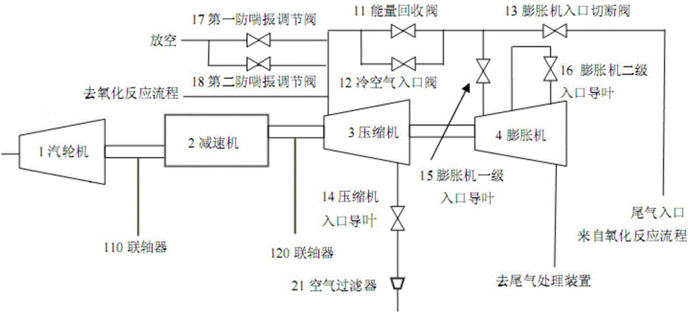
[0042] Such as figure 1 As shown, the present invention includes a steam turbine 1, a reducer 2, a compressor 3, an expander 4 and an auxiliary system to form a compressor unit; wherein, the steam turbine 1 is connected to the reducer 2 through a first coupling 110 to form a drive source unit; The reducer 2 forms a steam turbine-driven compressor unit through the second coupling 120 and the compressor 3; the compressor 3 forms an expander-driven compressor unit through the second coupling 120 and the expander 4; the steam turbine and the expander are formed through two If they are connected by a coupling, the two share the auxiliary system to complete the steam power balance of the device.

[0043] The auxiliary system includes an energy recovery valve 11, a cold air inlet valve 12, an expander inlet shut-off valve 13, a compressor inlet guid...


PUM


Abstract

The invention relates to an energy recycling control method for a PTA device. The energy recycling control method is characterized by comprising the following steps that the inlet temperature and the outlet temperature of a compressor, the inlet pressure, the outlet pressure and the outlet flow are measured; the pore plate differential pressure is converted into the square of the inlet flow qr<2> to serve as the transverse coordinate of an anti-surge curve; the outlet pressure and the inlet pressure of the compressor are converted into the pressure ratio Rc to serve as the longitudinal coordinate of the anti-surge curve; a dynamic anti-surge control curve is obtained according to the square of the inlet flow qr<2> and the pressure ratio Rc; the distance d between a working point and a surge point is obtained according to the dynamic anti-surge control curve; the DEV value, namely DEV=d-2b, is obtained according o the set safety margin b; and an energy recycling valve is controlled according to the DEV value. The energy recycling valve is controlled through an anti-surge control method, the requirement for reliable operation of the compressor is met, and the extremely-high stability performance is achieved. The working point of the compressor is near the anti-surge curve in a following manner, the unit efficiency is achieved to the maximum degree, the valve is usually in a completely-closed state, and it is ensured that the energy is not lost during use.

Description

technical field [0001] The invention relates to a control method of an energy recovery valve, in particular to a control method of an energy recovery valve externally connected to a compressor used in a PTA device. Background technique [0002] The air compressor unit is the core equipment of the PTA device. In addition to the task of transporting a large amount of air, it also needs to undertake the functions of energy balance and exhaust gas utilization of the device. The operating parameters of the compressor include the temperature, pressure, vibration, sealing gas volume, lubricating oil pressure, and the speed of the steam turbine between the various stages of the compressor. [0003] Such as figure 1 The schematic diagram of the compressor system in the PTA device is shown. The air is sent in through the air filter, and then enters through the inlet guide vane of the compressor. The inlet guide vane of the compressor can be adjusted. Different guide vane angles corre...

Claims


Application Information

Patent Timeline
Patent Type & Authority Applications(China)
IPC IPC(8): F04D29/66F04D27/00F01D15/00
Inventor 宋颖梅张宇田盛李晨
Owner SHENYANG BLOWER WORKS GRP AUTOMATIC CONTROL SYST ENG
Why Eureka
Try Eureka