
Bottom valve assembly of shock absorber

A shock absorber and bottom valve technology is applied in the structural field of the new shock absorber bottom valve assembly to achieve the effects of improving performance, reducing contact area, and improving response speed

Inactive Publication Date: 2016-03-02
成都九鼎科技(集团)有限公司
View PDF6 Cites 0 Cited by
  • Summary
  • Abstract
  • Description
  • Claims
  • Application Information

AI Technical Summary

Problems solved by technology

[0003] The purpose of the present invention is to solve the above-mentioned technical problems existing in the existing shock absorber bottom valve assembly, to provide a shock absorber bottom valve assembly that can effectively improve the performance of the shock absorber and reduce the difficulty of processing and assembly

Method used


Image

  • Bottom valve assembly of shock absorber
  • Bottom valve assembly of shock absorber
  • Bottom valve assembly of shock absorber

Examples


Embodiment Construction

[0019] The present invention will be further described below in conjunction with the accompanying drawings.

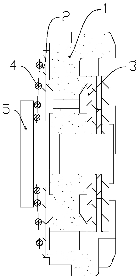
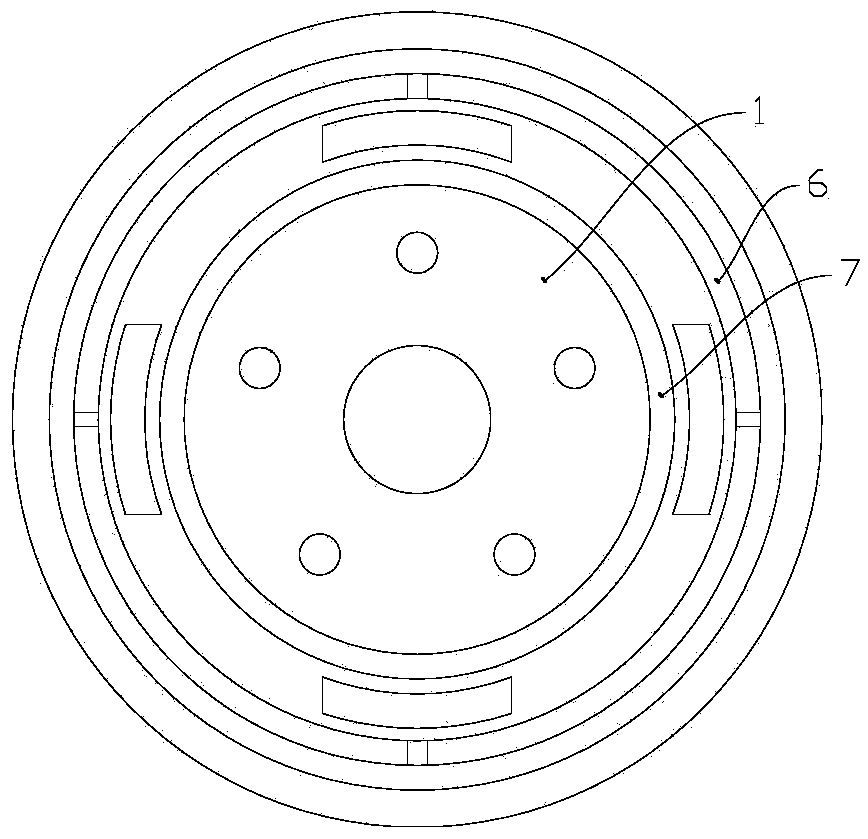
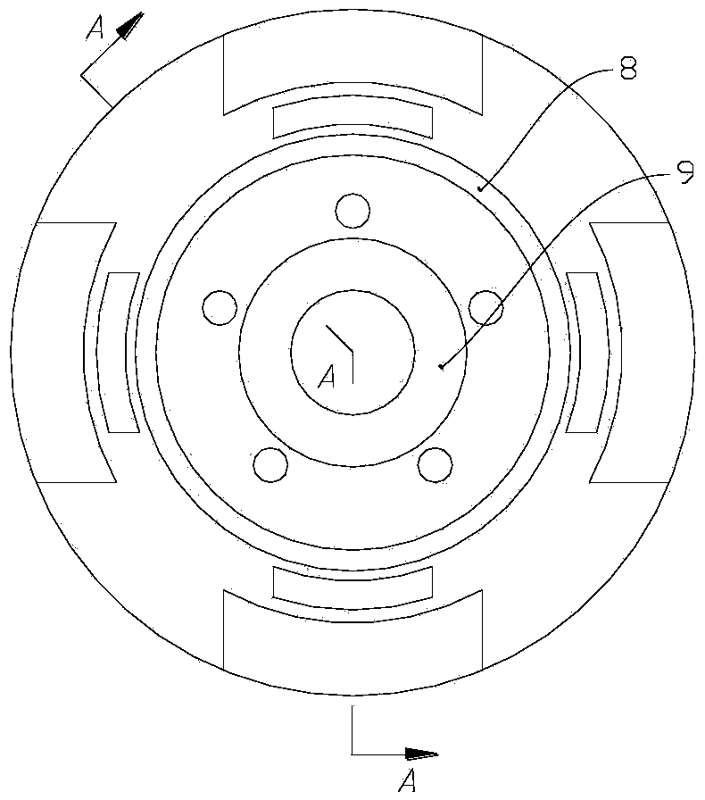
[0020] Such as Figures 1 to 4 As shown, it is a shock absorber bottom valve assembly, including a valve seat 1, a flow valve plate 2 and a spring 4 are provided on the left side of the valve seat 1, an adjustable valve plate 3 is provided on the right side of the valve seat 1, and the spring 4. The circulation valve piece 2, the valve seat 1 and the adjustable valve piece 3 are fixed by rivets 5 to form a bottom valve assembly; the valve seat 1 in the bottom valve assembly is provided with two layers of valve lines on the left and right sides respectively, respectively It is the outer valve line and the inner valve line, the end faces of the left outer valve line 6 and the left inner valve line 7 are matched with the flow valve piece 2, the end faces of the right outer valve line 8 and the right inner valve line 9 are adjustable The valve pieces 3 are matched, and th...


PUM


Abstract

The invention discloses a bottom valve assembly of a shock absorber. The bottom valve assembly comprises a valve seat, a circulation valve plate arranged at the left side of the valve seat, and an adjustable valve plate arranged at the right side of the valve seat. The left side and the right side of the valve seat are each provided with two layers of valve lines, namely the outer valve line and the inner valve line, wherein the height of the outer valve lines at the left side and the right side is larger than that of the corresponding inner valve lines. The outer valve lines and the inner valve lines of the valve seat have a certain height difference, the width of the end face of each valve line is reduced, and therefore the quality and the product percent of pass of the bottom valve assembly are improved, and the usability of the shock absorber is improved.

Description

technical field [0001] The invention relates to the technical field of shock absorbers, in particular to a novel shock absorber bottom valve assembly structure. Background technique [0002] With the continuous improvement of people's requirements for the comfort of automobiles, the performance and quality requirements of automobile shock absorbers are also higher and higher. At present, the composite gas-filled two-way hydraulic shock The structure can adjust the damping force required by the main engine factory, so that the shock absorber can achieve a good vibration reduction effect, and at the same time, it can better eliminate the distortion of the external characteristics and achieve better NVH performance. To improve the damping effect of the shock absorber, it is necessary to continuously debug the structure of the shock absorber valve system. The existing shock absorber bottom valve assembly is usually composed of a valve seat and a valve plate. The damping force i...

Claims


Application Information

Patent Timeline
Patent Type & Authority Applications(China)
IPC IPC(8): F16F9/34
Inventor 何洪波严茂张勇
Owner 成都九鼎科技(集团)有限公司
Learn More