
Diaphragm pump head

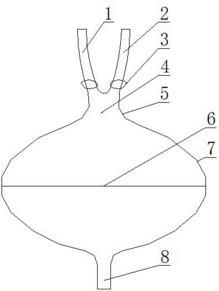
A diaphragm pump and diaphragm technology, applied in the field of medical devices, can solve the problems of thrombus formation on the inner wall of the casing, increase the application cost, and affect the service life of the diaphragm pump head, so as to reduce the risk of thrombosis, improve work efficiency, and improve service life. Effect

Inactive Publication Date: 2016-03-09
TIANJIN WELCOME MEDICAL EQUIP
View PDF8 Cites 2 Cited by
  • Summary
  • Abstract
  • Description
  • Claims
  • Application Information

AI Technical Summary

Problems solved by technology

Working principle: positive and negative pressures are applied through the pressure inlet and outlet pipes, causing the diaphragm to vibrate and pump the blood in and out. When pumping out, it is easy to generate a circulation pause in the shell of the diaphragm pump head, which will easily cause thrombus to form on the inner wall of the shell, affect the service life of the diaphragm pump head, and increase the application cost

Method used


Image

  • Diaphragm pump head

Examples


Embodiment Construction

[0019] The present invention will be further described in detail below through the specific examples, the following examples are only descriptive, not restrictive, and cannot limit the protection scope of the present invention with this.

[0020] A diaphragm pump head includes a casing 7 and a diaphragm 6 fixed in the casing, and the casing is made of hard plastic. The diaphragm is an elastically deformable diaphragm. A pressure inlet and outlet 8 is formed on the housing corresponding to one side of the diaphragm, and a blood inlet and outlet 4 is formed on the corresponding housing on the other side of the diaphragm. The pressure inlet and outlet are set corresponding to the center of the diaphragm. The blood inlet and outlet are set corresponding to the center of the diaphragm. One end of the blood inlet and outlet is connected to the housing, and the other end of the blood inlet and outlet is connected to the blood inlet pipe 1 and the blood outlet pipe 2 at the same tim...


PUM


Abstract

The invention relates to a diaphragm pump head. The diaphragm pump head comprises a shell and a diaphragm fixedly arranged in the shell. A pressure inlet and outlet is formed in the portion, corresponding to one side of the diaphragm, of the shell, a blood inlet and outlet is formed in the portion, corresponding to the other side of the diaphragm, of the shell, one end of the blood inlet and outlet is communicated with the shell, and the other end of the blood inlet and outlet is simultaneously communicated with a blood inflow pipe and a blood outflow pipe. Through the structural arrangement, thrombi can be effectively avoided, the service life is prolonged, and use cost is reduced.

Description

technical field [0001] The invention belongs to the field of medical equipment, in particular to a diaphragm pump head. Background technique [0002] Diaphragm pump head is a new type of bionic blood pump, which can be widely used in heart surgery to replace the heart for extracorporeal blood circulation and auxiliary devices for heart failure. The diaphragm pump head includes a housing and a diaphragm installed in the housing. The housing on one side of the diaphragm is provided with a pressure inlet and outlet pipe, and the housing on the other side of the diaphragm is respectively provided with an inlet blood vessel and an outlet blood vessel. Working principle: positive and negative pressures are applied through the pressure inlet and outlet pipes, causing the diaphragm to vibrate and pump the blood in and out. When pumping out, it is easy to generate a circulation pause in the casing of the diaphragm pump head, thereby easily causing thrombus to form on the inner wall ...

Claims


Application Information

Patent Timeline
Patent Type & Authority Applications(China)
IPC IPC(8): A61M1/10A61M1/36
CPCA61M1/3621A61M2210/12A61M60/268
Inventor 胡伟闻
Owner TIANJIN WELCOME MEDICAL EQUIP
Learn More