Upper rear drainage-type waterwheel of waterwheel type hydraulic generator

A hydroelectric generator and waterwheel technology, which is applied in the direction of hydroelectric power generation, impact engines, engine components, etc., can solve the problems of increasing the difficulty and cost of waterwheels, so as to improve water energy utilization efficiency, increase flow efficiency, The effect of improving the utilization rate of potential energy and kinetic energy

Inactive Publication Date: 2016-03-09
罗富强
View PDF7 Cites 4 Cited by
  • Summary
  • Abstract
  • Description
  • Claims
  • Application Information

AI Technical Summary

Problems solved by technology

However, this type of waterwheel-shaped direct wash-down turbine can only use the water head equal to or lower than the central shaft of the waterwheel. Once the water head is higher than the central shaft of the waterwheel, the pressure generated by the water flow higher than the central shaft of the waterwheel will form. The water entry resistance of the blades of

Method used


Image

  • Upper rear drainage-type waterwheel of waterwheel type hydraulic generator
  • Upper rear drainage-type waterwheel of waterwheel type hydraulic generator
  • Upper rear drainage-type waterwheel of waterwheel type hydraulic generator

Examples


Embodiment Construction

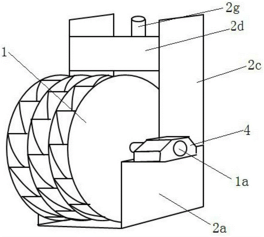
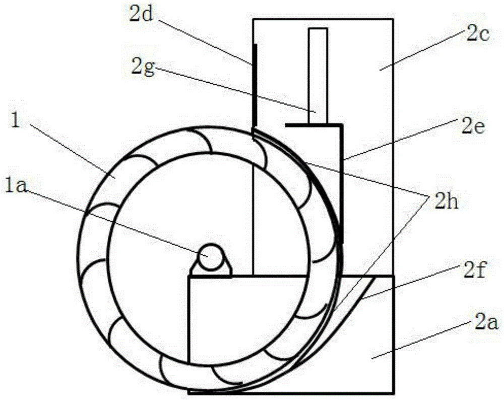
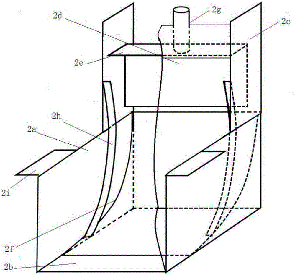
[0014] Such as figure 1 , figure 2 The upper and rear diversion type waterwheel of the shown hydroelectric generator includes a waterwheel 1 that can be driven to rotate along the central rotating shaft 1a by relying on the momentum of water flow, gravity and pressure, and a water guide body that guides the water flow into the bucket of the waterwheel. The water diversion body such as image 3 As shown, it includes a water diversion and diversion tank and a water diversion and diversion box arranged above the water diversion side of the water diversion and diversion tank. The water diversion and diversion tank includes two tank body side baffles 2a, a bottom plate 2b, and a gradually lowering and narrowing rear arc-shaped diversion baffle 2f that guides the water flow to the bucket at the lower part of the waterwheel. . The water diversion and diversion box includes two upper side baffles 2c at the top of the side baffles in the water inlet direction of the tank body and a...


PUM


Abstract

Disclosed is an upper rear drainage-type waterwheel of a waterwheel type hydraulic generator. The upper rear drainage-type waterwheel of the waterwheel type hydraulic generator comprises a waterwheel body (1) and a water diversion and flow guiding body. The water diversion and flow guiding body comprises a water diversion and flow guiding trench and an upper water diversion and flow guiding box. The water diversion and flow guiding trench comprises two trench body side baffles (2a), a bottom plate (2b) and an arc flow guiding baffle (2f) which guides water flow to a water bucket of the lower part of the water inlet side of the waterwheel body. The water diversion and flow guiding box comprises two upper side baffles (2c) and a flow baffle (2d) which is connected between the front ends of both the upper side baffles. An L-shaped anti-back-pressure water diversion and flow guiding plate (2e) of which the inner angle faces the waterwheel body is disposed in the water diversion and flow guiding box. The lower half part of the water inlet side of the waterwheel body is disposed in the water diversion and flow guiding trench and the upper half part of the water inlet side of the waterwheel body is disposed in the water diversion and flow guiding box. The water flow enters water buckets of both the upper part and lower part of the water inlet side of the waterwheel body respectively along a transverse plate of the anti-back-pressure water diversion and flow guiding plate and the arc flow guiding baffle of the back of the water diversion and flow guiding trench, and the waterwheel is driven to rotate through join forces. According to the upper rear drainage-type waterwheel of the waterwheel type hydraulic generator, hydraulic energy can be efficiently utilized, and the power generation capacity of the waterwheel type hydraulic generator is substantially improved.

Description

technical field [0001] The invention belongs to the technical field of hydraulic generators. Background technique [0002] Existing types of waterwheel-type hydroelectric generators are mainly divided into three categories. The first category is to place the waterwheel directly in the canal and use the impact force of the water flow to generate electricity. This type of waterwheel power generation belongs to the most primitive waterwheel The vehicle utilization method mainly relies on the impact of the flow velocity of the water flow to rotate the waterwheel to drive the generator to generate electricity. Because only the impact kinetic energy of the water flow is used, the utilization rate of the potential energy of the water flow is very low, and the power generation efficiency is very low. It is impossible to build a hydropower station with a large installed capacity, and it does not have the ability to scale industrially. The second type is to make the waterwheel into a...

Claims


Application Information

Patent Timeline
IPC IPC(8): F03B1/00F03B1/02F03B11/00
CPCY02E10/20
Inventor 罗富强
Owner 罗富强
Why Eureka
Try Eureka