
Pipeline device for high-density plasma stock

A plasma, remote plasma technology, applied in the field of semiconductor equipment, to achieve the effect of reducing metal pollution problems

Inactive Publication Date: 2016-03-09
SHANGHAI HUALI MICROELECTRONICS CORP
View PDF6 Cites 4 Cited by
  • Summary
  • Abstract
  • Description
  • Claims
  • Application Information

AI Technical Summary

Problems solved by technology

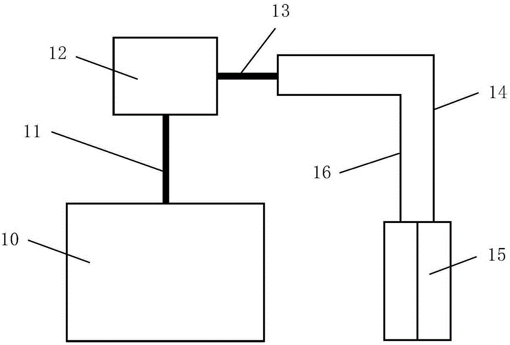
[0006] The purpose of the present invention is to overcome the above-mentioned defects existing in the prior art, and provide a pipeline device of a high-density plasma machine, which can reduce the problem of metal pollution in the STI etching process

Method used


Image

  • Pipeline device for high-density plasma stock
  • Pipeline device for high-density plasma stock

Examples


Embodiment Construction

[0021] The specific embodiment of the present invention will be further described in detail below in conjunction with the accompanying drawings.

[0022] It should be noted that, in the following specific embodiments, when describing the embodiments of the present invention in detail, in order to clearly show the structure of the present invention for the convenience of description, the structures in the drawings are not drawn according to the general scale, and are drawn Partial magnification, deformation and simplification are included, therefore, it should be avoided to be interpreted as a limitation of the present invention.

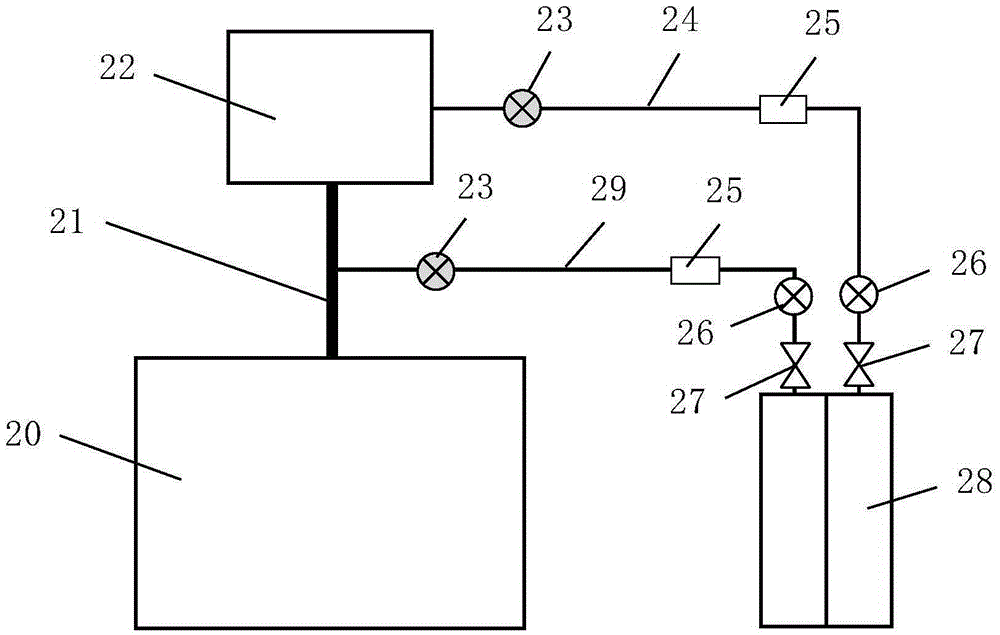
[0023] In the following specific embodiments of the present invention, please refer to figure 2 , figure 2 It is a structural schematic diagram of a pipeline device of a high-density plasma machine in a preferred embodiment of the present invention. Such as figure 2 As shown, the pipeline device of a high-density plasma machine of the present i...


PUM


Abstract

The invention discloses a pipeline device for a high-density plasma stock. An NF3 gas for cleaning a cavity and an NF3 gas for participating in an etching process respectively adopt an independent first branch pipe and a second branch pipe to enter the cavity, the NF3 gas for participating in the etching process can directly enter the stock cavity without through a remote plasma system, and thus, the fact that during an STI etching process, due to corrosion of the NF3 gas for participating in the etching process, metal elements are left in the inner cavity of the remote plasma system can be avoided, and metal pollution problems caused by metal element over specification during the STI etching process can be reduced.

Description

technical field [0001] The invention relates to the technical field of semiconductor equipment, and more particularly, to a gas pipeline device that can reduce metal pollution in STI process and is applied to a high-density plasma machine. Background technique [0002] The high-density plasma machine process is to form a thin film on the surface of a silicon wafer by chemical vapor deposition of a specific process gas under plasma-enhanced conditions in a high-temperature environment in the cavity. For example, AMAT (America Applied Materials Semiconductor Equipment Co., Ltd.) HDP (high density plasma, high density plasma) machine is characterized by fast film forming speed, good film uniformity, and strong hole filling ability. Among them, the STI (Shallow Trench Isolation, Shallow Trench Isolation) process is one of the main processes provided by its cavity. [0003] As the line width of integrated circuits gradually decreases, the problem of filling voids is increasingly...

Claims


Application Information

Patent Timeline
IPC IPC(8): H01J37/32
CPCH01J37/3244H01J2237/3174
Inventor 刘涛龚荟卓
Owner SHANGHAI HUALI MICROELECTRONICS CORP
Learn More