rotary compressor
A rotary compressor and rotary shaft technology, applied in rotary piston machines, rotary piston pumps, mechanical equipment, etc., can solve problems such as the inability to ensure the sealing of cylinder chambers, simplify structure and assembly, reduce leakage losses, Elimination of restrictions on the diameter of the suction piping
- Summary
- Abstract
- Description
- Claims
- Application Information
AI Technical Summary
Problems solved by technology
Method used
Image
Examples
no. 1 Embodiment approach
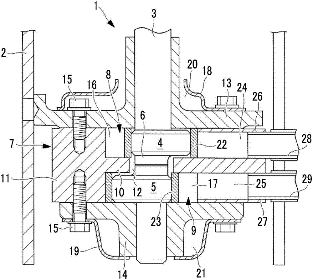
[0035] Below, use figure 1 , the first embodiment of the present invention will be described.
[0036] figure 1 A longitudinal sectional view of the rotary compressor according to the first embodiment of the present invention is shown in .
[0037] The rotary compressor 1 of the present embodiment can be applied to a single-stage multi-cylinder rotary compressor or a multi-stage rotary compressor, and here, a two-cylinder type hermetic rotary compressor including two cylinders is exemplified. This rotary compressor 1 is configured to include a hermetic casing 2, and a rotary compression mechanism 7 driven via a rotary shaft (crankshaft) 3 is provided in the hermetic casing 2 by an electric motor (not shown) provided in an upper portion of the hermetic casing 2. lower part.
[0038] The upper part of the rotating shaft (crankshaft) 3 is combined with the rotor of the electric motor, and is rotated by the electric motor, and the lower part is provided with a first eccentric s...
no. 2 Embodiment approach
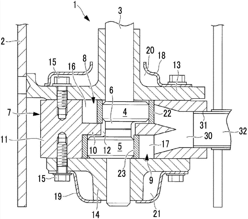
[0059] Next, use figure 2 A second embodiment of the present invention will be described.
[0060] In this embodiment, the configurations of the suction port 30 and the suction pipe connection hole 31 are different from those of the first embodiment described above. The other points are the same as those of the first embodiment, and thus description thereof will be omitted.
[0061] In this embodiment, if figure 2 As shown, a large common suction port 30 that is branched across the partition plate 10 and communicates with the plurality of cylinder chambers 16 and 17 is provided, and a large common suction port 30 that communicates with the suction port 30 is provided. A single thick suction pipe 32 can be connected to the common suction pipe connection hole 31 .
[0062] In this way, the suction port 30 is set as a common suction port 30 that is branched across the partition plate 10 and communicates with the plurality of cylinder chambers 16, 17, and a common suction por...
no. 3 Embodiment approach
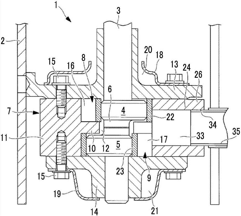
[0065] Next, use image 3 A third embodiment of the present invention will be described.
[0066] In this embodiment, the configurations of the suction port 33 and the suction pipe connection hole 34 are different from those of the first embodiment described above. The other points are the same as those of the first embodiment, and thus description thereof will be omitted.
[0067] In this embodiment, if image 3 As shown, a large common suction port 33 communicating with the plurality of cylinder chambers 16 and 17 across the partition plate 10 is provided, and a large common suction pipe communicating with the suction port 33 is provided. The connection hole 34 allows connection of one relatively thick suction pipe 35 .
[0068]In this way, the suction port 33 is set as one common suction port 33 communicating with the plurality of cylinder chambers 16, 17 across the partition plate 10, and one common suction piping connection hole is provided in communication with the su...
PUM
 Abstract
Description
Claims
Application Information
 - R&D
- Intellectual Property
- Life Sciences
- Materials
- Tech Scout
- Unparalleled Data Quality
- Higher Quality Content
- 60% Fewer Hallucinations
Browse by: Latest US Patents, China's latest patents, Technical Efficacy Thesaurus, Application Domain, Technology Topic, Popular Technical Reports.
© 2025 PatSnap. All rights reserved.Legal|Privacy policy|Modern Slavery Act Transparency Statement|Sitemap|About US| Contact US: help@patsnap.com


