A double-proportioning-valve-controlled liquid fertilizer application system capable of timely amount changing

A valve-controlled, double-proportional technology, applied in the field of agricultural equipment, can solve the problems of liquid fertilizer flow and pressure restrictions, and the amount of liquid fertilizer that is difficult to apply, so as to reduce losses, improve the efficiency of liquid fertilizer use, and achieve fast fertilizer efficiency.

Inactive Publication Date: 2016-03-16
NORTHEAST AGRICULTURAL UNIVERSITY
View PDF6 Cites 2 Cited by
  • Summary
  • Abstract
  • Description
  • Claims
  • Application Information

AI Technical Summary

Problems solved by technology

The device has high requirements on the shape of the groove of the proportional ring, and it is difficult to achieve continuous stepless variable liquid fertilizer application. Due to the limitation of the groove of the proportional ring and the liquid fertilizer channel size of the external gear valve body, the liquid fertilizer in the liquid fertilizer output conduit Flow and pressure are also restricted

Method used


Image

  • A double-proportioning-valve-controlled liquid fertilizer application system capable of timely amount changing

Examples


Embodiment approach 1

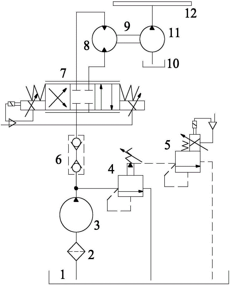
[0016] This embodiment includes the following components: hydraulic oil tank 1, filter 2, hydraulic pump 3, quick connector 6, electro-hydraulic proportional directional valve 7, hydraulic motor 8, coupling 9, liquid fertilizer tank 10, liquid spray pump 11, liquid spray Tube 12.

[0017] The inlet of the hydraulic pump 3 is connected to the hydraulic oil tank 1 through the filter 2, the outlet of the hydraulic pump 3 is connected to the outlet pipeline, and the outlet pipeline is connected to the electro-hydraulic proportional directional valve 7 through the quick joint 6. The electro-hydraulic proportional directional valve 7 includes four oil The ports are the oil inlet, the oil return port, the first oil outlet and the second oil outlet respectively, wherein the quick connector 6 is connected with the oil inlet, the oil return port leads to the hydraulic oil tank 1, the first oil outlet and the The second oil outlet is respectively connected to the two oil ports of the hyd...

Embodiment approach 2

[0020] On the basis of Embodiment 1, a pilot relief valve 4 is added. The pilot overflow valve 4 communicates with the outlet pipeline between the hydraulic oil tank 1 and the hydraulic pump 3 and the quick connector 6 respectively. The pilot relief valve 4 plays the role of overload protection, and the set pressure is 6MPa. When the hydraulic oil pressure in the outlet pipeline exceeds 6MPa, the pilot relief valve 4 opens, and the hydraulic oil flows through the pilot relief valve 4. , back to the hydraulic oil tank 1.

Embodiment approach 3

[0022] On the basis of the second embodiment, an electro-hydraulic proportional overflow valve 5 is added. The electro-hydraulic proportional relief valve 5 communicates with the hydraulic oil tank 1 and the pilot relief valve 4 respectively. The remote control port is connected to the electro-hydraulic proportional relief valve 5. The function of this valve is to realize stepless control of the system pressure through electric signals. When the hydraulic oil pressure in the outlet pipeline does not exceed the set pressure, and the operator wants to control the liquid injection When the injection flow rate of the liquid fertilizer in the pipe 12 is controlled, the electro-hydraulic proportional relief valve 5 is controlled so that the hydraulic oil in the outlet pipeline flows back to the hydraulic oil tank 1 through the electro-hydraulic proportional relief valve 5 after passing through the pilot relief valve 4, and the electro-hydraulic proportional relief valve 5 returns to ...


PUM


Abstract

The objective of the invention is to provide a double-proportioning-valve-controlled liquid fertilizer application system capable of timely amount changing. The system comprises a hydraulic fuel tank, a liquid injection pipe, a liquid injection pump, a hydraulic motor and an electric-hydraulic proportional direction valve. The hydraulic pump is connected to the hydraulic fuel tank. A filter is disposed between the hydraulic pump and the hydraulic fuel tank. The electric-hydraulic proportional direction valve comprises a fuel inlet, a fuel return port, a first fuel outlet and a second fuel outlet. The hydraulic pump is connected to the fuel inlet of the electric-hydraulic proportional direction valve through a pipe. A quick coupling is mounted on the pipe. The fuel return port of the electric-hydraulic proportional direction valve is communicated with the hydraulic fuel tank. The first fuel outlet and the second fuel outlet of the electric-hydraulic proportional direction valve are respectively communicated with the inlet and the outlet of the hydraulic motor. The output shaft of the hydraulic motor is connected to a fuel injection pump through a coupling. The fuel injection pump is separately communicated with a liquid fertilizer tank and the liquid injection pipe. The system achieves timely-amount-changing fertilization of liquid fertilizers according to different actual agricultural production requirements, achieves an objective of accurate control, increases the using efficiency of the liquid fertilizers, promotes rapid production of desired fertilizer effects, and reduces loss.

Description

technical field [0001] The invention relates to an agricultural implement, in particular to a mechanism for applying liquid fertilizer. Background technique [0002] In order to improve fertilizer utilization rate, fast fertilizer effect and less loss, some research experts propose to apply liquid fertilizer. Liquid fertilization is a fertilization technology in agricultural production, and has become an important research direction in the development of fertilization technology. At present, the fertilization method of liquid fertilizer needs to open a fertilizer ditch on the soil surface, and apply liquid fertilizer continuously and quantitatively in the ditch. The liquid fertilizer fertilization system cannot realize timely variable control, which reduces the utilization rate of liquid fertilizer. [0003] The patent with the publication number CN102934558A titled "Adjustable Fertilizer for Liquid Fertilization" discloses a liquid fertilizer fertilization device driven by...

Claims


Application Information

Patent Timeline
Patent Type & Authority Applications(China)
IPC IPC(8): A01C23/04
CPCA01C23/04A01C23/007
Inventor 李杞超姜微孙文峰
Owner NORTHEAST AGRICULTURAL UNIVERSITY
Why Eureka
Try Eureka