Self-suction negative pressure vibration sieve

A vibrating sieve and self-priming technology, which is applied in the direction of mobile filter element filter, filtration separation, separation device, etc., can solve the problems of small processing capacity and high liquid content of discharged cuttings, so as to reduce liquid content and increase treatment The effect of reducing the amount of processing work and reducing processing costs

Inactive Publication Date: 2016-03-16
徐小弟
View PDF5 Cites 6 Cited by
  • Summary
  • Abstract
  • Description
  • Claims
  • Application Information

AI Technical Summary

Problems solved by technology

[0003] The invention provides a self-priming negative pressure vibrating screen to solve the problems of small processing capacity and high liquid content of discharged cuttings in the prior art

Method used


Image

  • Self-suction negative pressure vibration sieve
  • Self-suction negative pressure vibration sieve

Examples


Embodiment Construction

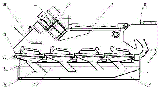
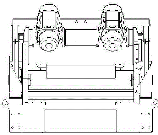
[0013] like figure 1 and figure 2 As shown, a self-priming negative pressure vibrating screen is mainly composed of a screen box 10, a vibrating motor 1, a screen 3, a liquid inlet funnel 8, a vibrating screen base 4, several negative pressure funnels 5 and a negative pressure tank 7. The net 3 is fixed on the screen base 11, the vibrating motor 1 is connected to the side plate of the screen box 10 through the motor base 2, the negative pressure funnel 5 is installed at the bottom of the screen support base 11 and connected to the vibrating screen base 4 through the liquid outlet 6 The negative pressure tank 7 forms a closed cavity through the drilling fluid. A liquid inlet funnel 8 is arranged on the side of the vibrating screen base 4. The outlet of the liquid inlet funnel 8 is located above the screen 3, and the drilling fluid baffle 9 is installed on the top of the screen 3 to prevent drilling. Liquid splash.

[0014] The working principle of the present invention is th...


PUM


Abstract

A self-suction negative pressure vibration sieve is mainly composed of a sieve box, a vibration motor, a screen, a liquid inlet funnel, a vibration sieve base, a plurality of negative pressure funnels and a negative pressure groove; the screen is fixed on a screen supporting base; the vibration motor is connected with a sieve box side plate frame by a motor base; the negative pressure funnels are arranged at the bottom of the screen and form a sealed cavity with the negative pressure groove on the vibration sieve base through liquid outlets and via a drilling fluid; the liquid inlet funnel is arranged at one side of the vibration sieve base, and an outlet of the liquid inlet funnel is located above the screen. According to the device, the plurality of negative pressure funnels are arranged below the screen, the drilling fluid and rock debris in the drilling fluid are separated in virtue of the negative pressure action, the treatment capacity of the vibration sieve is increased, the liquid content of the rock debris is greatly reduced, the subsequent treatment work intensity and treatment costs are reduced, and the self-suction negative pressure vibration sieve is more environmentally friendly.

Description

technical field [0001] The invention relates to the technical field of drilling auxiliary equipment, in particular to a self-priming negative pressure vibrating screen. Background technique [0002] The drilling fluid shale shakers in the existing drilling solids control system all work under open or semi-open conditions, the screen surface and below the screen surface are both atmospheric pressure, and the flow of drilling fluid through the screen mainly depends on the vibration movement of the screen surface It is realized by the inertial force generated by the drilling fluid and the potential energy of the drilling fluid itself. In order to make the drilling fluid have a greater ability to penetrate the screen, it is usually necessary to increase the vibration intensity of the vibrating screen, but the increase in the vibration intensity will cause serious splashing of the drilling fluid, and at the same time, the solids such as cuttings contained in the drilling fluid ar...

Claims


Application Information

Patent Timeline
IPC IPC(8): B01D33/03B01D33/64E21B21/01
CPCB01D33/0353B01D33/64B01D2221/04E21B21/01
Inventor 徐小弟易昕楠徐阳祺
Owner 徐小弟
Why Eureka
Try Eureka