
Adjustable cathode fixing device for high-voltage wet electrostatic precipitator

A technology of wet electrostatic precipitator and cathode fixation, which is applied in the direction of electrode conveying device, external electrostatic separator, electrostatic separation, etc., can solve the problems of uneven electrode spacing, low operating efficiency, and inability to operate at full load, so as to solve the problem of flue gas escape, improve operating efficiency, and solve the effect of insulation failure

Inactive Publication Date: 2016-03-16
SHANDONG GUOSHUN CONSTR GRP
View PDF8 Cites 2 Cited by
  • Summary
  • Abstract
  • Description
  • Claims
  • Application Information

AI Technical Summary

Problems solved by technology

[0003] One is that the negative girder of the upper air chamber is loaded by the insulators inside the insulation box outside the tower, and is suspended under the suspension rod in the sealed side pipe under the insulation box. The bypass of the gas to the clean flue gas causes a large amount of untreated dusty flue gas to escape. The cathode beam is laid on the cathode girder, and the cathode wire is fixed between the upper and lower beams. The thermal expansion of the cathode wire and the binding tension force The tightness is inconsistent, and the pole spacing is different after the slack deviation occurs, resulting in failure to operate at full load or even flashover and disconnection accidents;
[0004] In particular, the lower cathodes of large-scale wet electrostatic precipitators connected in parallel with multiple electric fields have insulation failure, flashover, disconnection, low operating efficiency, and long-term safe and standard operation.

Method used


Image

  • Adjustable cathode fixing device for high-voltage wet electrostatic precipitator
  • Adjustable cathode fixing device for high-voltage wet electrostatic precipitator
  • Adjustable cathode fixing device for high-voltage wet electrostatic precipitator

Examples


Embodiment Construction

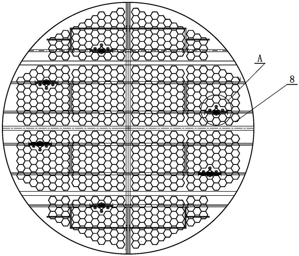
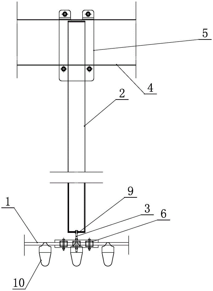
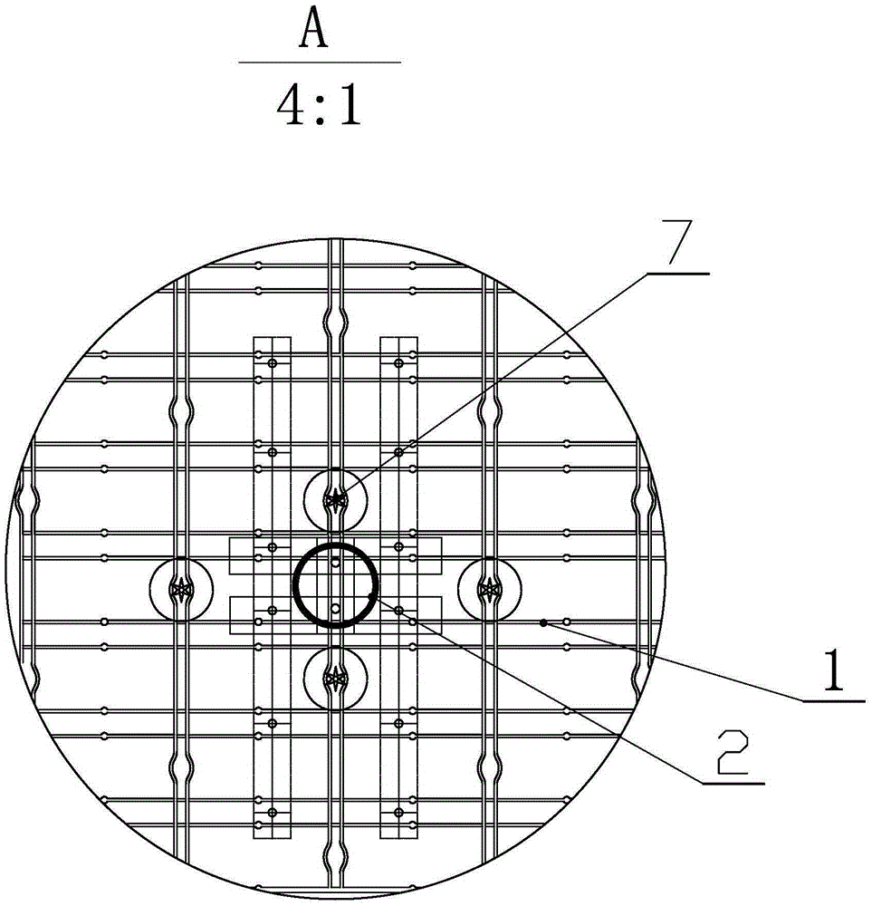
[0026] The following is attached Figure 1-6 The features and principles of the present invention are described in detail, and the examples given are only used to explain the present invention, not to limit the protection scope of the present invention.

[0027] like Figure 1-6 As shown, the invention includes a cathode frame 1, a cathode fixing pile 2, a connection channel between the cathode frame of the upper air chamber and the cathode frame of the lower air chamber, an adjustment bolt 3, a cathode beam 4 and a cathode beam clamping flange 5.

[0028] The cathode frame is provided with channel steel 6 for connecting the frame with cathode fixing piles, and several cathode wire tensioning weights 10 are provided on the cathode frame. The channel steel is buckled on the cathode frame to increase the connection rigidity between the cathode frame and the adjusting bolt. The cathode girder is located above the cathode frame, and the cathode pile is welded on one of the flang...


PUM


Abstract

The invention discloses an adjustable cathode fixing device for a high-voltage wet electrostatic precipitator. A cathode frame is provided with groove steel for a cathode fixing pile to be connected with the frame. A cathode girder is located above an anode pipe of the cathode frame and is fixed through two clamping flanges and clamping bolts. The cathode fixing pile is arranged between the cathode girder and the cathode frame and is installed in a connection channel between the cathode girder of an upper air chamber and the cathode frame of a lower air chamber. A cathode wire is laid in the anode pipe in the channel. An adjusting bolt is fixed to the bottom of the cathode fixing pile, a screw rod of the adjusting bolt penetrates through the groove steel and the cathode frame, and an adjusting nut matched with the adjusting bolt is arranged below the cathode frame. The adjustable cathode fixing device is suitable for treatment of exhaust gas of large power stations, exhaust gas of sintering machines, pellets, cement and chemical engineering of the iron and steel industry and a large amount of exhaust gas of the nonferrous metallurgy industry. Ultra-low emission improvement is carried out on existing power plants and steel mills and is of great significance in high efficiency and energy conservation advocated by the country and long-term safe, stable and standard operation of a system.

Description

technical field [0001] The invention relates to the technical field of smoke and dust treatment equipment, in particular to an adjustable cathode fixing device for a high-pressure wet electrostatic precipitator. Background technique [0002] At present, the domestic existing technology adopts two fixing methods for the cathode: [0003] One is that the negative girder of the upper air chamber is loaded by the insulators inside the insulation box outside the tower, and is suspended under the suspension rod in the sealed side pipe under the insulation box. The bypass of the gas to the clean flue gas causes a large amount of untreated dusty flue gas to escape. The cathode beam is laid on the cathode girder, and the cathode wire is fixed between the upper and lower beams. The thermal expansion of the cathode wire and the binding tension force The tightness is inconsistent, and the pole spacing is different after the slack deviation occurs, resulting in failure to operate at ful...

Claims


Application Information

Patent Timeline
IPC IPC(8): B03C3/86B03C3/16
CPCB03C3/86B03C3/16
Inventor 吕茂新任尚坤范贤平孙德山赵民尹承磊吴力菊周成
Owner SHANDONG GUOSHUN CONSTR GRP
Learn More