Numerically-controlled machining centre body

A machining center and machine body technology, applied in metal processing machinery parts, metal processing, metal processing equipment, etc., can solve the problems of damaged sealing plates, unreliable limit of protective doors, etc., and achieve the effect of improving safety performance and reliable limit.

Active Publication Date: 2016-03-16
GUANGZHOU SNIMAY HOME FURNITURE CO LTD
View PDF6 Cites 1 Cited by
  • Summary
  • Abstract
  • Description
  • Claims
  • Application Information

AI Technical Summary

Problems solved by technology

There is a sealing plate on the frame, and the sealing plate is fixed on the frame by screws. After the screws are fixed, the screw head is directly pressed on the sealing plate, which may damage the sealing plate
In addition, in order to prevent chips, coolant, etc. from splashing out during the machining process, there are push-pull protective doors on the frame. Of course, there are flip-type protective doors, but the limit of the protective door is not reliable.

Method used


Image

  • Numerically-controlled machining centre body
  • Numerically-controlled machining centre body
  • Numerically-controlled machining centre body

Examples


Embodiment Construction

[0034] The present invention will be further described in detail below in conjunction with the accompanying drawings and specific embodiments.

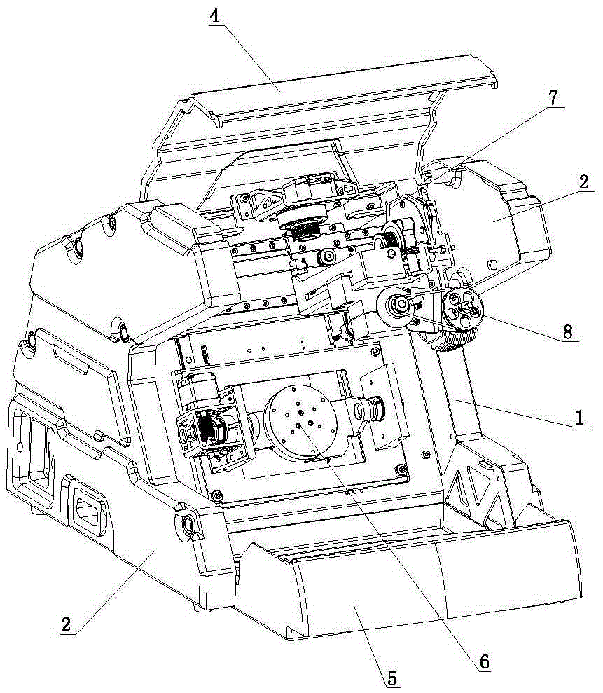
[0035] Such as Figure 1 to Figure 3 As shown, the CNC machining center includes a frame 1, a side cover 2, a rear cover 3, a protective cover 4, a material receiving device 5, a workbench device 6, a vertical arm device 7 and a spindle device 8.

[0036] Such as Figure 4 with Figure 5 As shown, the frame 1 includes side frames 11 , connecting rods 12 and vertical plates 13 . Side frames 11 are respectively fixed at both ends of the connecting rod 12 , and the vertical plate 13 is fixed between the two side frames 11 .

[0037] Such as Figure 6 with Figure 7 As shown, the side frame 11 includes a side panel 111, and the side panel 111 includes a front side panel 1111 and a rear side panel 1112, the rear side panel 1112 is connected to the front side panel 1111, and the height of the front side panel 1111 is lower than that of...


PUM


Abstract

The invention discloses a numerically-controlled machining centre body. The numerically-controlled machining centre body comprises a rack, side covers, a rear cover and a protective cover, wherein the rack comprises side frames, connection rods and a vertical plate; each side cover comprises a side cover plate and a side cover flange formed by being bent inwards from the edge of the side cover plate; a second installation hole is arranged in each side cover plate, a sunken part is formed on the each cover plate and in the corresponding second installation hole, a convex ring is arranged in each sunken part in a manner of being corresponding to the corresponding second installation hole, and a connection column is arranged on the inner wall of each side cover plate and at a position corresponding to the corresponding second installation hole; each side cover is installed at the outer side of the corresponding side frame, each connection column contacts with the corresponding side frame, and a screw penetrates through each second installation hole and is connected to the corresponding side frame; the protective cover comprises a cover body, a hinge lug and a limit element; and limit blocks are arranged at the two sides of the front end of the flange of the cover body. The numerically-controlled machining centre body disclosed by the invention is capable of better protecting the side covers, reliably limiting the protective cover, and preventing the protective cover from entering the rack.

Description

technical field [0001] The invention relates to a numerical control machining center. Background technique [0002] CNC milling machine is an automatic processing equipment developed on the basis of general milling machine. The processing technology of the two is basically the same, and the structure is somewhat similar. CNC milling machines are divided into two categories without tool magazine and with tool magazine. Among them, the CNC milling machine with tool magazine is also called machining center. [0003] In addition to the characteristics of ordinary milling machine processing, CNC milling processing has the following characteristics: [0004] 1. Parts processing has strong adaptability and flexibility, and can process parts with particularly complex contours or difficult to control sizes, such as mold parts, shell parts, etc. [0005] 2. It can process parts that cannot be processed by ordinary machine tools or are difficult to process, such as complex curve par...

Claims


Application Information

Patent Timeline
Patent Type & Authority Applications(China)
IPC IPC(8): B23Q1/01B23Q37/00B23Q11/08
CPCB23Q1/015B23Q11/08B23Q37/00
Inventor 沈正福
Owner GUANGZHOU SNIMAY HOME FURNITURE CO LTD
Why Eureka
Try Eureka