
Injection mold for foot pad of computer case

A computer case and injection mold technology, applied in the field of injection molds, can solve the problems of low production efficiency, unreasonable design, cumbersome processes, etc., and achieve the effects of high production efficiency, simple and scientific structure design, and low mold cost.

Inactive Publication Date: 2016-03-16
广州市花都区花山精宏塑胶模具厂
View PDF8 Cites 4 Cited by
  • Summary
  • Abstract
  • Description
  • Claims
  • Application Information

AI Technical Summary

Problems solved by technology

[0004] The present invention aims at the disadvantages of unreasonable design, low production efficiency, cumbersome process and high cost in existing injection molds, and provides a mold with reasonable design, simple structure, high production efficiency and low cost

Method used


Image

  • Injection mold for foot pad of computer case
  • Injection mold for foot pad of computer case
  • Injection mold for foot pad of computer case

Examples


Embodiment example

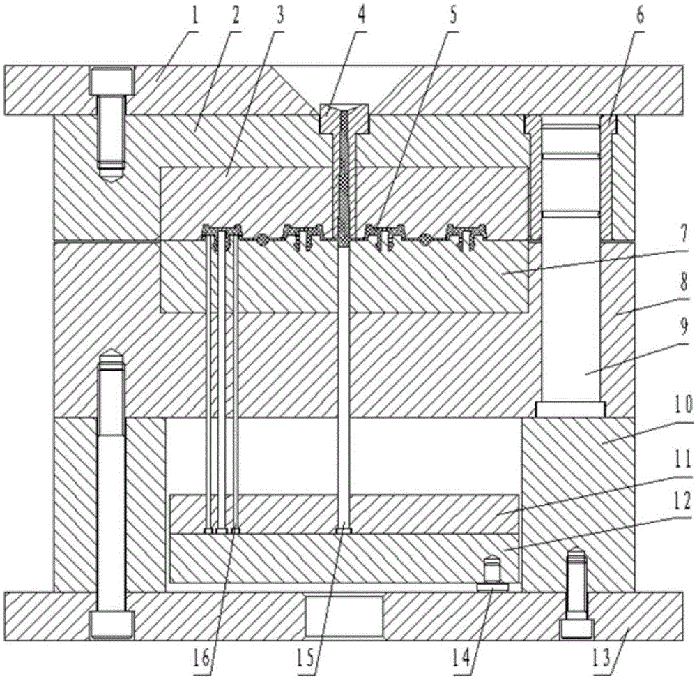
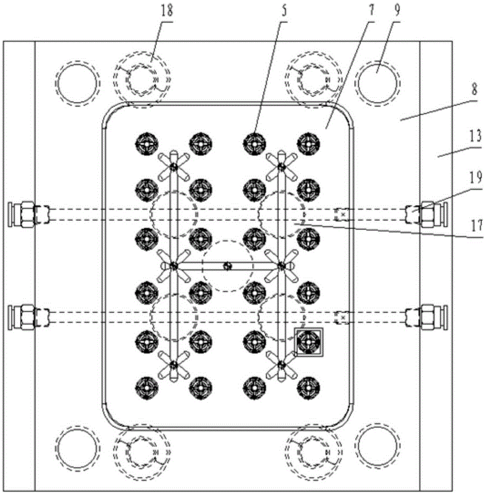
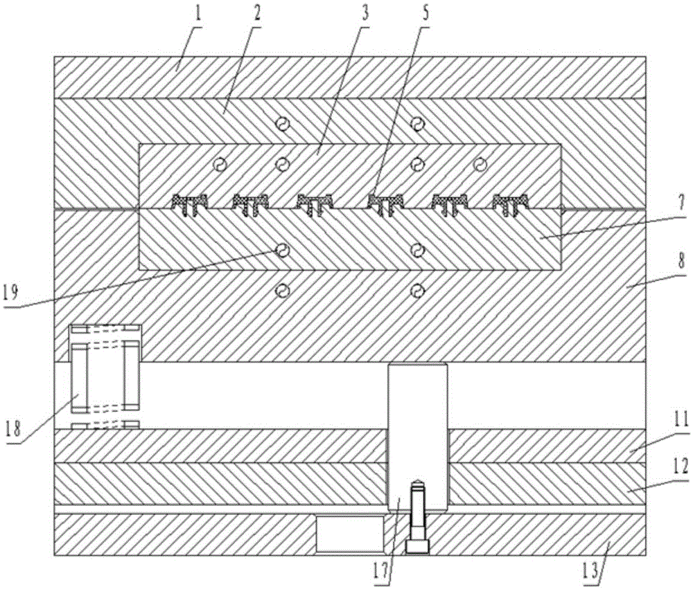
[0028] Such as figure 1 As shown, the computer case foot pad injection mold described in the embodiment of the present invention includes a fixed mold and a movable mold. and a cooling water channel, the upper end surface of the die fixing plate is provided with the upper template, the die fixing plate is provided with a step hole matching the sprue sleeve, and the sprue sleeve is arranged on the step In the hole, the die fixing plate is provided with a square groove matching the die insert, the die insert is arranged in the square groove, the die fixing plate and the die insert The blocks are provided with cooling water channels, the die insert is provided with a cavity matching the chassis foot pad, the die fixing plate is provided with a guide sleeve hole matching the guide sleeve, and the guide sleeve Set in the hole of the guide sleeve; the movable mold includes a punch insert, a punch fixing plate, a guide column, a support plate, a thimble fixing plate, a thimble backi...


PUM


Abstract

The invention discloses an injection mold for a foot pad of a computer case. The injection mold comprises a fixed mold body and a movable mold body. The fixed mold body comprises an upper mold plate, a concave mold fixing plate, a concave mold insert, a sprue bush, mold cavities, a guide sleeve and cooling water channels. The movable mold body comprises a convex mold insert, a convex mold fixing plate, guide columns, supporting plates, an ejector pin fixing plate, an ejector pin cushion plate, a lower mold plate, a stop pin, a sprue puller, double-joint round ejector pins, supporting columns, return pins and cooling water channels. The fixed mold body and the movable mold body are matched and connected through the guide column and the guide sleeve. The 10 cooling water channels are arranged in the injection mold for the foot pad of the computer case, so that cooling time is short, and production efficiency is high; the four supporting columns are arranged, so that the materials of the supporting plates can be reduced, and the mold cost is low; the 24 mold cavities are adopted for injection molding at the same time, so that production efficiency is high; and a convex mold and a concave mold are both made to be of an insert structure, so that replacement is convenient, and the mold cost is low.

Description

technical field [0001] The invention relates to an injection mold, in particular to an injection mold for a foot pad of a computer case. Background technique [0002] Injection molding (Injection Molding) refers to the method in which heated and melted materials are injected into the mold cavity from a state of high temperature, high pressure and high speed, and after cooling and solidification, plastic products can be obtained. This method is suitable for mass production of parts with complex shapes and is one of the important processing methods. The injection molding process can be roughly divided into the following six stages: "mold closing-injection-holding pressure-cooling-mold opening-product removal". The above process is repeated to continuously produce plastic products. [0003] However, the injection mold design of the existing computer case foot pads is unreasonable, low production efficiency, cumbersome process and high cost (the foot pads need to be used with s...

Claims


Application Information

Patent Timeline
Patent Type & Authority Applications(China)
IPC IPC(8): B29C45/26B29C45/32B29C45/73
CPCB29C45/2602B29C45/32B29C45/7312
Inventor 罗建光王权周红庄
Owner 广州市花都区花山精宏塑胶模具厂
Learn More