
A flat-top pulse magnetic field generating device and a flat-top pulse current generating device

A flat-top pulse and generating device technology, applied in the field of strong magnetic fields, can solve the problems of large volume and complex structure, and achieve the effects of small volume, simple magnet structure and low overall cost

Active Publication Date: 2016-04-20
HUAZHONG UNIV OF SCI & TECH
View PDF5 Cites 5 Cited by
  • Summary
  • Abstract
  • Description
  • Claims
  • Application Information

AI Technical Summary

Problems solved by technology

[0008] In view of the above defects or improvement needs of the prior art, the present invention provides a flat-top pulse current and magnetic field generating device, the purpose of which is to generate a flat-top magnetic field without ripples, thereby solving the need for a pulse generator to generate a flat-top pulse magnetic field Power sources such as battery packs or high energy storage capacitors require the design and construction of large and complex magnets and other technical issues

Method used


Image

  • A flat-top pulse magnetic field generating device and a flat-top pulse current generating device
  • A flat-top pulse magnetic field generating device and a flat-top pulse current generating device
  • A flat-top pulse magnetic field generating device and a flat-top pulse current generating device

Examples


Embodiment Construction

[0025] In order to make the object, technical solution and advantages of the present invention clearer, the present invention will be further described in detail below in conjunction with the accompanying drawings and embodiments. It should be understood that the specific embodiments described here are only used to explain the present invention, not to limit the present invention. In addition, the technical features involved in the various embodiments of the present invention described below can be combined with each other as long as they do not constitute a conflict with each other.

[0026] The invention belongs to electromagnetic devices, and more specifically relates to a flat-top pulse magnetic field generating device and a flat-top pulse current generating device. It is used in scientific experiments such as nuclear magnetic resonance and specific heat measurement.

[0027] The pulsed magnetic field refers to the magnetic field generated in the coil space by using the p...


PUM


Abstract

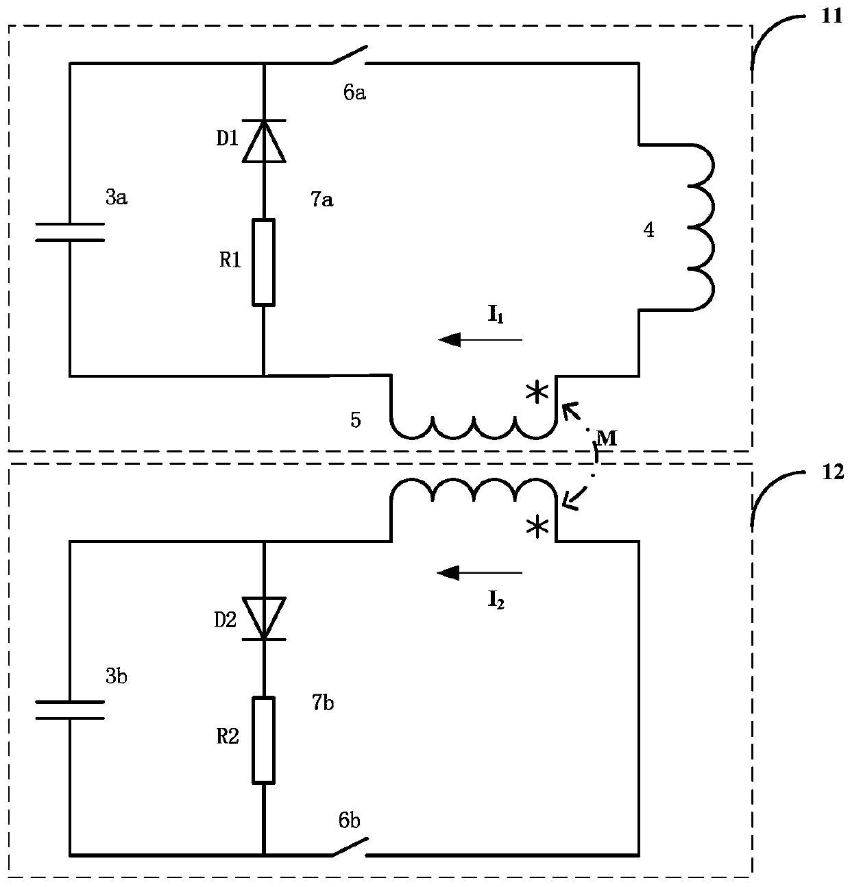
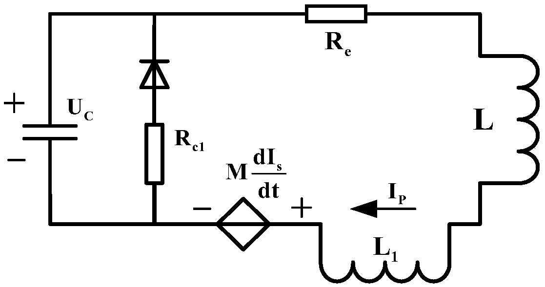
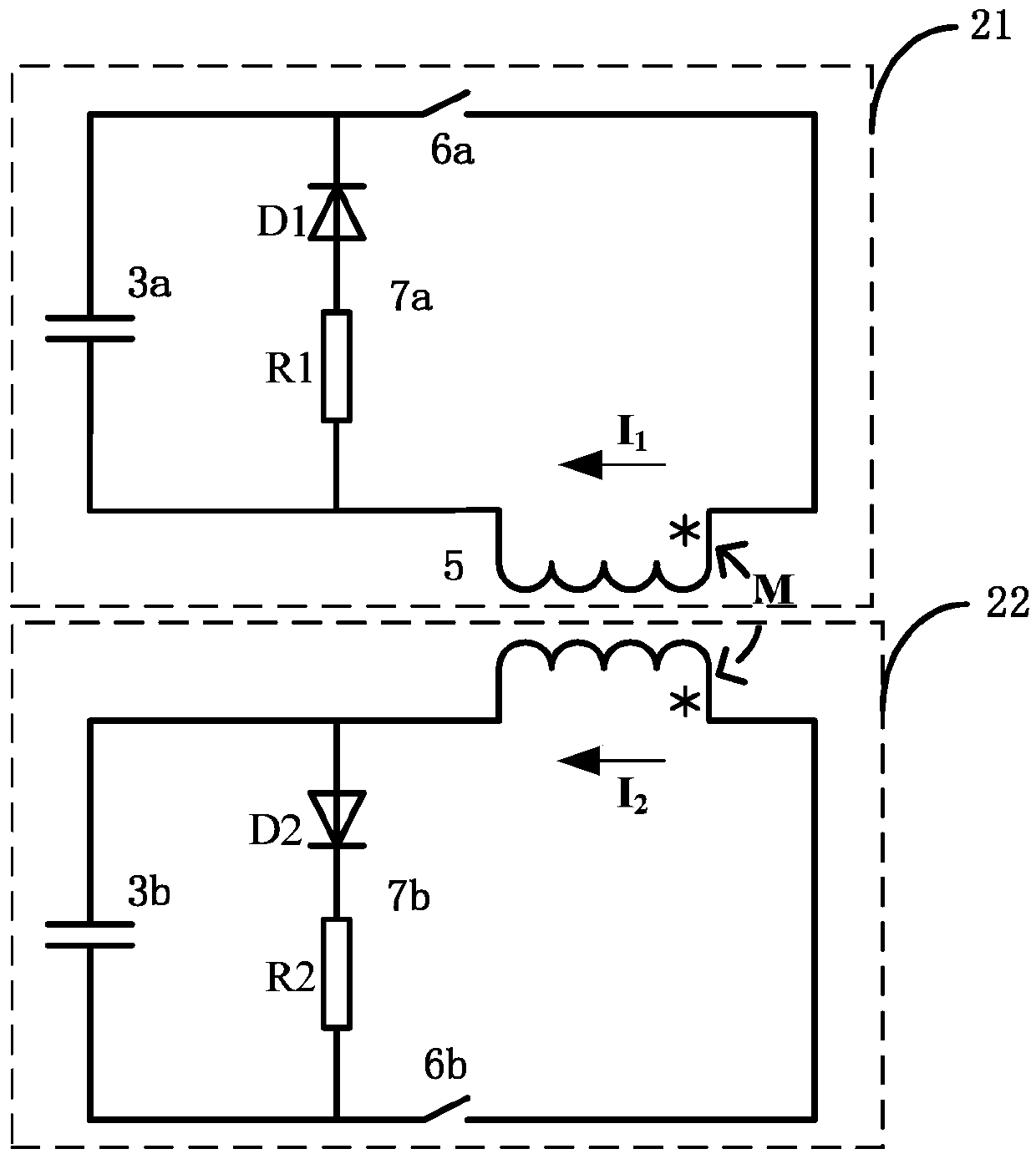
The invention provides a flat-topped pulse magnetic field generating device and a flat-topped pulse current generating device. The flat-topped pulse magnetic field generating device comprises a transformer, a first loop and a second loop, wherein the first loop is formed by serial connection of primary side coils of the transformer, a first capacitor, a first switch and a magnet in sequence, and the second loop is formed by serial connection of secondary side coils of the transformer, a second capacitor and a second switch in sequence. The first loop further comprises first follow current loops connected to the two ends of the first capacitor in parallel, and the second loop further comprises second follow current loops connected to the two ends of the second capacitor in parallel. Each first follow current loop comprises a first resistor and a first one-way conducting element, wherein the first resistor and the first one-way conducting element are sequentially connected to the two ends of the first capacitor. Each second follow current loop comprises a second resistor and a second one-way conducting element, wherein the second resistor and the second one-way conducting element are sequentially connected to the two ends of the second capacitor. Flat-topped currents / magnetic fields can be generated through the coupling effect of the primary side coils and the secondary side coils of the transformer, and the flat-topped pulse magnetic field generating device and the flat-topped pulse current generating device have the advantages that manufacturing cost is low, the process is simple, circuit control is convenient and quick, and the flat-topped currents / magnetic fields do not have ripple waves.

Description

technical field [0001] The invention belongs to the field of strong magnetic field technology, and more specifically relates to a flat-top pulse magnetic field generating device and a flat-top pulse current generating device. Background technique [0002] The rail-type electromagnetic drive system has become a hot spot in the field of electromagnetic emission. During the working process of the rail-type electromagnetic drive system using a solid armature, the sliding performance of the solid armature is related to its own structural shape, size, and material properties. The output waveform of the current is related. In order to enable the solid armature to withstand higher charge and discharge energy and achieve a higher exit velocity, the output pulse current should be modulated as much as possible according to the flat-top principle in electromagnetic emission. At the same time, the flat top current is also conducive to good contact between the solid armature and the guid...

Claims


Application Information

Patent Timeline
Patent Type & Authority Patents(China)
IPC IPC(8): H02M9/04
Inventor 李亮彭涛蒋帆赵健龙丁洪发
Owner HUAZHONG UNIV OF SCI & TECH
Learn More