Damping limit adjusting mechanism of furniture side sliding door

A technology of adjusting mechanism and side sliding door, which is applied in the directions of windows/doors, building components, and wing sash arrangement, etc. It can solve the problem of unfavorable door body assembly, unable to meet user needs, unable to adjust the upper and lower positions of door body and guide wheel, etc. problems, to prevent the failure of buffer closing, facilitate interaction, and smooth the sliding opening and closing process.

Active Publication Date: 2016-03-16
伍志勇
View PDF8 Cites 10 Cited by
  • Summary
  • Abstract
  • Description
  • Claims
  • Application Information

AI Technical Summary

Problems solved by technology

It is said that this structure can automatically adjust the tight fit between the double guide wheels and the guide rails; however, it cannot adjust the upper and lower positions between the door body and the guide wheels, which is not conducive to the assembly of the door body and cannot meet the needs of users

Method used


Image

  • Damping limit adjusting mechanism of furniture side sliding door
  • Damping limit adjusting mechanism of furniture side sliding door
  • Damping limit adjusting mechanism of furniture side sliding door

Examples


no. 1 example

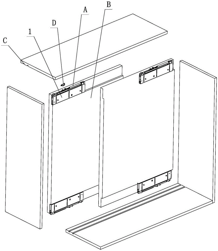
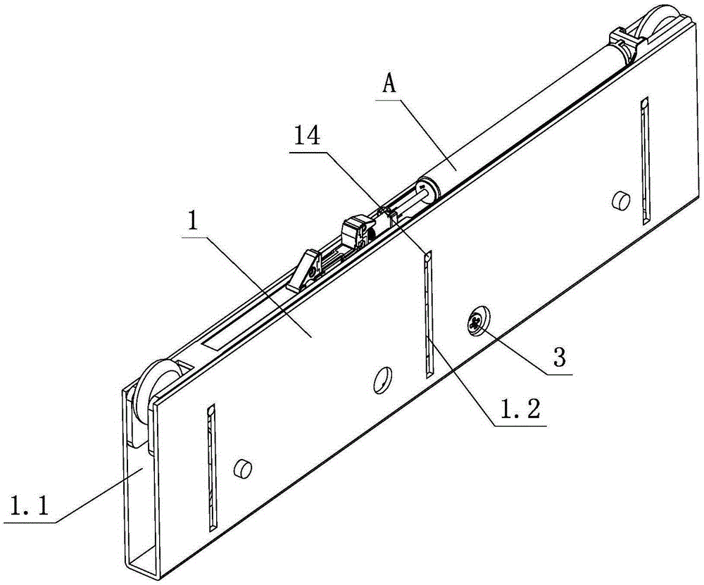
[0031] see Figure 1-Figure 10The damping limit adjustment mechanism of the side sliding door of this furniture includes a damping device A and a fixed frame 1, an elastic part 2 is arranged between the damping device A and the fixed frame 1, and the damping device A elastically slides on the fixed frame 1 through the elastic part 2 Above; the damping device A or the fixed frame 1 is provided with a limit adjustment device, the limit adjustment device at least includes an adjustment element, and the function part 3 of the adjustment element is actuated by a tool or manually to make the distance between the damping device A and the fixed frame 1 The relative position between them is changed, and the elastic sliding stroke between the damping device A and the fixed frame 1 is adjusted in a limited position.

[0032] Further, the damping device A is arranged on the fixed frame 1, and includes a damper 4, a positioning element 5, a pushing element 6, a spring 7 and a rolling eleme...

no. 2 example

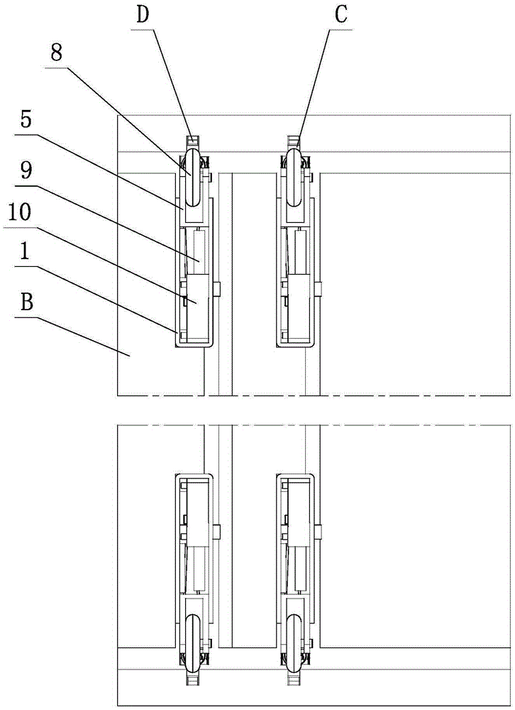
[0044] see Figure 11-Figure 16 , the damping limit adjustment mechanism of the furniture side sliding door, which is different from the first embodiment in that: the limit adjustment device is arranged on the fixed frame 1, and includes an adjustment element, an actuating element 9, an assembly element 10 and a transmission Teeth 12, wherein the assembly element 10 is arranged on the fixed frame 1, the adjusting element is an adjusting screw 13 arranged horizontally or vertically, and one end thereof is provided with an active part 3 toward the front or side of the fixed frame 1, and the middle part is provided with a screw part 13.1, The other end is provided with a screw rotating part 13.2. The transmission tooth 12 is positioned and rotated on the assembly element 10 and meshes with the screw part 13.1 of the adjustment screw 13. The actuating element 9 linearly slides on the assembly element 10 and is set corresponding to the transmission tooth 12. There is a rack part 9....


PUM


Abstract

The invention discloses a damping limit adjusting mechanism of a furniture side sliding door. The damping limit adjusting mechanism comprises a damping device and a fixed frame; an elastic piece is arranged between the damping device and the fixed frame; the damping device elastically slides on the fixed frame through the elastic piece; a limit adjusting device is arranged on the damping device or the fixed frame, and at least includes an adjusting element; and an acting part of the adjusting element is acted manually or through a tool, so that relative positions of the damping device and the fixed frame are changed to limit and adjust the elastic sliding travel between the damping device and the fixed frame. Through structural improvement, the damping limit adjusting mechanism has such characteristics as simple and reasonable structure, reliable performance, quick adjustment, convenience for operation, accurate positioning, strong bearing capacity, smooth opening / closing process and less force, and is strong in practicability.

Description

technical field [0001] The invention relates to a side sliding door for furniture, in particular to a damping limit adjustment mechanism for a side sliding door for furniture. Background technique [0002] The Chinese patent literature number is CN204238725U, which discloses a sliding door guide wheel device on April 1, 2015, which includes a base plate, a support plate, a spring, a bolt, a first guide wheel, a second guide wheel, and a limit pin. The first guide wheel and the second guide wheel are arranged side by side on the support plate; the support plate is provided with a through hole, the base plate is provided with a threaded hole, and one end of the spring outer ring is fixed on the right end of the base plate; the nut end of the bolt is fixed to the support plate. The threaded end passes through the through hole and the inner ring of the spring to be threaded with the threaded hole in turn, and one end of the inner ring of the spring is located between the bolt an...

Claims


Application Information

Patent Timeline
IPC IPC(8): E06B3/46E05D13/00E05D15/06E05F5/08
CPCE05D13/00E05D15/0626E05F5/003E05F5/08E05Y2900/20E06B3/4663
Inventor 伍志勇
Owner 伍志勇
Why Eureka
Try Eureka