
Current linear control circuit for constant current source

A technology of linear control and constant current source, applied in the direction of control/regulation system, regulation of electrical variables, instruments, etc., can solve the problems of easily damaged electrical components, rapid circuit changes, inconvenient adjustment, etc., to achieve stable circuit performance and prevent current Too large to avoid damage to electrical components

Active Publication Date: 2016-03-16
BOZHON PRECISION IND TECH CO LTD
View PDF6 Cites 2 Cited by
  • Summary
  • Abstract
  • Description
  • Claims
  • Application Information

AI Technical Summary

Problems solved by technology

[0004] For this reason, the technical problem to be solved by the present invention lies in the current linear control circuit used in the constant current source in the prior art, which is inconvenient to adjust, and it is easy to cause sudden and rapid changes in the circuit during the adjustment process, and the electric device is easily damaged when the current is too large , the security is poor, so a current linear control circuit for constant current source is proposed

Method used


Image

  • Current linear control circuit for constant current source

Examples


Embodiment Construction

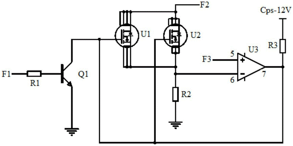
[0019] like figure 1 As shown, the current linear control circuit for a constant current source of the present invention includes: a triode Q1, a first field effect transistor U1, a second field effect transistor U2, an operational amplifier U3, a first resistor R1, a second resistor R2, The third resistor R3.

[0020] The base of the triode Q1 is connected to the first network node F1 through the first resistor R1, the emitter of the triode Q1 is grounded, and the collector of the triode Q1 is connected to the gate of the first field effect transistor U1 and the The gate of the second field effect transistor U2. In this embodiment, the triode Q1 is an NPN low-power triode whose model is 9013. The function of the transistor Q1 is to switch and control the gate of the first field effect transistor U1. The first network node F1 is a control terminal for controlling the on-off of the triode Q1, the first resistor R1 is a current-limiting base resistor, and the first resistor R...


PUM


Abstract

The invention discloses a current linear control circuit for a constant current source. the circuit comprises a triode Q1, a first field effect transistor U1, a second field effect transistor U2, an operational amplifier U3, a first resistor R1, a second resistor R2 and a third resistor R3. The output end of the operational amplifier is connected with the grids of the two field effect transistors, and then the sources of the two field effect transistors are connected with the second input end of the operational amplifier. In this way, a closed-loop negative feedback is formed. Through adjusting the voltage of a third network node and applying a high level on a first network node, a second network node is enabled to output a current of a certain value. In this way, the current linear adjustment of the current source is realized. The current value is convenient to adjust and stable in adjustment process, while the sudden rapid change of the circuit is avoided. Through arranging the above two field effect transistors, the current is prevented from getting too large to damage electrical devices. The circuit is high in safety, stable in performance, simple in design, low in cost and wide in application range, so that the circuit can be widely applied to simple constant current sources.

Description

Technical field: [0001] The invention belongs to the technical field of constant current source circuits, and in particular relates to a current linear control circuit for constant current sources. Background technique: [0002] The constant current source circuit is the basis to be able to provide a stable current to ensure the stable operation of other circuits. The constant current source circuit is mainly composed of an input stage and an output stage, the input stage provides a reference current, and the output stage outputs the required constant current. That is to say, the constant current source circuit is required to output a constant current, so the device as the output stage should have a volt-ampere characteristic of a saturated output current. It is usually implemented by using BJT or MOSFET working in the output current saturation state. There are two types of constant current sources, one is imported high-precision source meters such as Agilent's B2911A, Adv...

Claims


Application Information

Patent Timeline
Patent Type & Authority Applications(China)
IPC IPC(8): G05F1/573
CPCG05F1/5735
Inventor 吕绍林杨愉强王建福谈贤红
Owner BOZHON PRECISION IND TECH CO LTD
Learn More