High-precision clock phase control circuit
A phase control circuit, high-precision clock technology, applied in single output arrangement, pulse shaping and other directions, can solve the problems of transistor state changing too late, occupying PCB board area, random misoperation, etc., to achieve low cost, high flexibility, high precision effect
- Summary
- Abstract
- Description
- Claims
- Application Information
AI Technical Summary
Problems solved by technology
Method used
Image
Examples
Embodiment 1
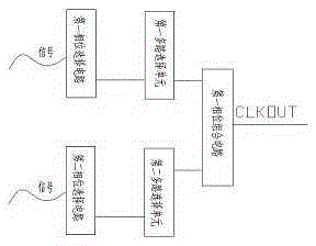
[0017] like figure 1 Show, a high -precision clock phase control circuit, including a multi -phase clock generated circuit module and a programmable phase selection circuit module.And at least one protective unit, the programmable phase selection circuit module includes multiple multi -road selection units and phase combination circuits, which are connected separately from a single multi -road selection circuit and a single phase selection circuit.
[0018] Among them, the selection unit contains an hour input and a signal input pink, which contains an hour input and one signal input pin.
[0019] Among them, the clock generated circuit module includes the first phase selection circuit, the second phase selection circuit and other phase phase selection circuits.
[0020] Among them, the multi -road selection unit includes the first multi -road selection unit, the second multi -road selection unit and other multi -way options.
[0021] Among them, the phase combination circuit incl...
Embodiment 2
[0027] The rest is the same as the embodiment 1. The difference is that the selection unit contains an hour input and one signal input.The clock input of the selection unit inputs the pin to receive a phase of the clock signal, using the signal of the selected unit to input the pin to receive a selection signal, and generates a one output signal based on the phase clock signal and the selection signal.The clock inputs the pin to receive the phase clock signal, and uses the one -signal input of the protective unit to input the pound of the switch signal to receive the encoding data, and use the other signal of the protective unit to enter the pound of the poundData, according to the clock signal of the phase and the coding data of the switching signal, generate a selection signal.
Embodiment 3
[0029] The rest is the same as the Example 1, the difference is that the selection unit contains two clock input pins and one signal input pins.The one -hour input of the selected unit inputs the pin to receive the current phase clock signal, and use the other clock of the selected unit to enter the pink to receive the previous phase of the clock signal, and use the signal of the selected unit to enter the pin to receive a selection signal to receive a selection signal.According to the multiple phase clock signals and the selection signal, a one -output signal is generated, and the clock input of the protective unit inputs to receive the current phase clock signal.The encoding data of the switching signal is used to input another coding data of the switch signal using the other signal of the protective unit, and generate the selection signal based on the current phase clock signal and the encoding data of the switching signal.
PUM
 Abstract
Description
Claims
Application Information
 - R&D
- Intellectual Property
- Life Sciences
- Materials
- Tech Scout
- Unparalleled Data Quality
- Higher Quality Content
- 60% Fewer Hallucinations
Browse by: Latest US Patents, China's latest patents, Technical Efficacy Thesaurus, Application Domain, Technology Topic, Popular Technical Reports.
© 2025 PatSnap. All rights reserved.Legal|Privacy policy|Modern Slavery Act Transparency Statement|Sitemap|About US| Contact US: help@patsnap.com

