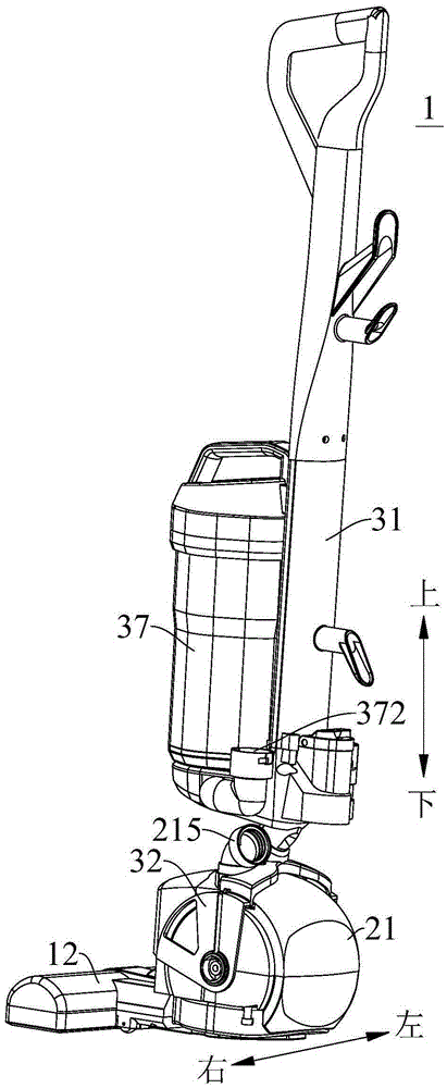
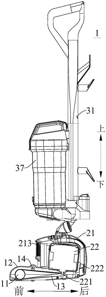
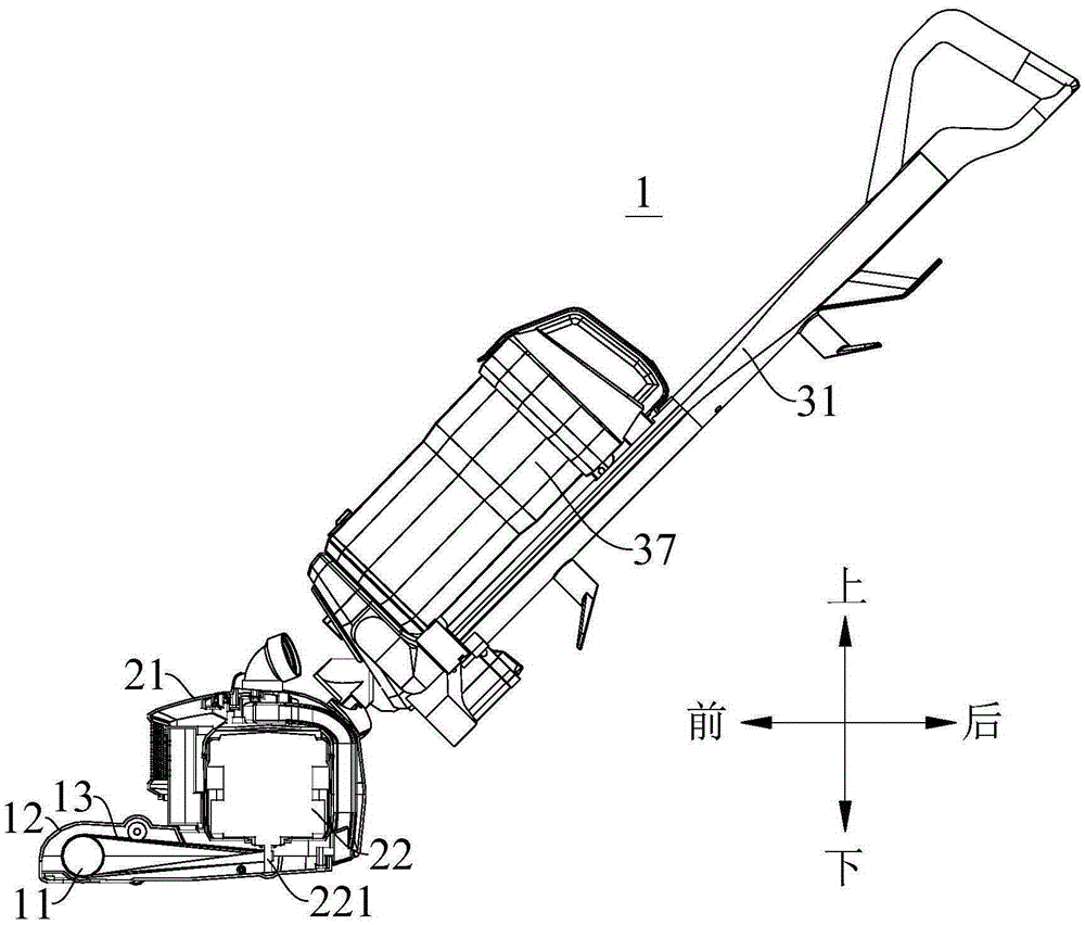
Clutch device of upright dust collector, and upright dust collector employing same

A technology for clutch devices and vacuum cleaners, which is applied in the installation of vacuum cleaners, electromechanical devices, and electrical equipment. It can solve the problems of increasing the floor space of the motor, limitations, and large volume of the motor cover, and achieves simple structure, convenient operation, and space occupation. small effect

Active Publication Date: 2016-03-23
JIANGSU MIDEA CLEANING APPLIANCES
View PDF8 Cites 6 Cited by
  • Summary
  • Abstract
  • Description
  • Claims
  • Application Information

AI Technical Summary

Problems solved by technology

[0002] The vacuum cleaner in the related art includes two motors to drive the roller brush and the fan respectively, wherein the motor driving the fan is generally arranged horizontally, that is, the motor shaft of the motor is parallel to the installation platform of the motor, which will cause the motor cover of the motor to be too large , which increases the footprint of the motor. At the same time, the motor arranged horizontally will bring great limitations to the layout of other parts of the vacuum cleaner.

Method used


Image

  • Clutch device of upright dust collector, and upright dust collector employing same
  • Clutch device of upright dust collector, and upright dust collector employing same
  • Clutch device of upright dust collector, and upright dust collector employing same

Examples


Embodiment Construction

[0071] Embodiments of the present invention are described in detail below, examples of which are shown in the drawings, wherein the same or similar reference numerals designate the same or similar elements or elements having the same or similar functions throughout. The embodiments described below by referring to the figures are exemplary and are intended to explain the present invention and should not be construed as limiting the present invention.

[0072] The following disclosure provides many different embodiments or examples for implementing different structures of the present invention. To simplify the disclosure of the present invention, components and arrangements of specific examples are described below. Of course, they are only examples and are not intended to limit the invention. Furthermore, the present invention may repeat reference numerals and / or letters in different instances. This repetition is for the purpose of simplicity and clarity and does not in itself...


PUM


Abstract

The invention discloses a clutch device of an upright dust collector, and the upright dust collector employing the clutch device. The clutch device is arranged between the motor component and the machine body component of the upright dust collector, the motor component comprises a motor housing and a motor arranged inside the motor housing, the machine body component comprises a machine body and a bridging part mounted on the machine body, the bridging part is rotatablely connected with the motor housing, the clutch device comprises a slideway and a trigger, one end of the trigger is matched with a sliding column inside the slideway in a sliding manner, and the other end of the trigger is provided with a shifter lever suitable for pulling the motor to move, when the bridging part drives the slideway to move, the sliding column slides along the slideway so as to enable the trigger to rotate, and when the trigger rotates, the shifter lever pulls the motor to rotate relative to the motor housing. According to the clutch device of the upright dust collector, provided by the embodiment of the invention, the purpose of driving the motor to rotate is achieved, adjustment to the tension of a driving belt is achieved, normal works of dust sweeping and dust sucking are ensured, the assembling and the de-assembling are convenient, the running is stable and reliable, and the work efficiency is high.

Description

technical field [0001] The invention relates to the field of cleaning machinery, in particular to a clutch device of an upright vacuum cleaner and an upright vacuum cleaner with the same. Background technique [0002] The vacuum cleaner in the related art includes two motors to drive the roller brush and the fan respectively, wherein the motor driving the fan is generally arranged horizontally, that is, the motor shaft of the motor is parallel to the installation platform of the motor, which will cause the motor cover of the motor to be too large , which increases the floor area of ​​the motor, and meanwhile, the horizontal arrangement of the motor will bring great limitations to the arrangement of other parts of the vacuum cleaner. Contents of the invention [0003] The present invention aims to solve at least one of the technical problems existing in the prior art. Therefore, the present invention proposes a clutch device for an upright vacuum cleaner. The clutch device...

Claims


Application Information

Patent Timeline
Patent Type & Authority Applications(China)
IPC IPC(8): A47L9/04A47L5/22A47L9/28A47L9/00H02K7/10
CPCA47L5/22A47L9/00A47L9/0411A47L9/0444A47L9/0477A47L9/2868H02K7/10
Inventor 胡卫
Owner JIANGSU MIDEA CLEANING APPLIANCES
Why Eureka
Try Eureka