
A shift control method for a dual-shaft parallel electric drive system for a vehicle

A technology of electric drive system and control method, which is applied in the direction of control drive, control device, electric power device, etc., which can solve the problems of insufficient efficiency of drive motor, poor acceleration, poor climbing ability, waste of electric energy, etc., and achieve improved acceleration. Performance and climbing performance, low cost, and the effect of reducing the cost of use

Active Publication Date: 2016-08-17
NANJING YUEBOO POWER SYST CO LTD
View PDF2 Cites 0 Cited by
  • Summary
  • Abstract
  • Description
  • Claims
  • Application Information

AI Technical Summary

Problems solved by technology

[0003] At present, the pure electric drive system widely used in the market includes: multi-speed transmission and traditional drive system with clutch, multi-speed transmission and drive system without clutch, two independent drive motors and fixed gear with drive shaft Transmission device, drive motor and primary reducer transmission device; among them, multi-speed transmission device and traditional drive system with clutch have better acceleration, but there is power interruption when shifting gears; multi-speed transmission device and drive system without clutch The transmission efficiency is high and there is no power interruption; the driving motor and the primary reducer transmission can realize stepless speed change, but the acceleration and climbing ability are poor, and the efficiency of the driving motor is not fully utilized
[0004] In addition, the car has different power requirements during the acceleration, low-speed and high-speed driving stages. If a single motor is used, it is difficult for the motor to work in the high-efficiency operating area all the time, which will easily cause waste of electric energy.

Method used


Image

  • A shift control method for a dual-shaft parallel electric drive system for a vehicle
  • A shift control method for a dual-shaft parallel electric drive system for a vehicle
  • A shift control method for a dual-shaft parallel electric drive system for a vehicle

Examples


Embodiment Construction

[0048] The specific embodiments of the present invention will be described in further detail below in conjunction with the accompanying drawings.

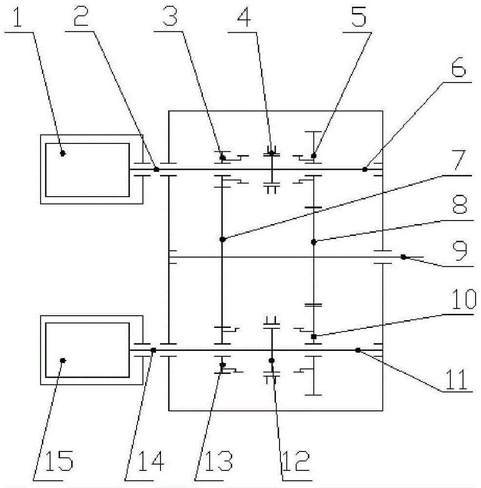
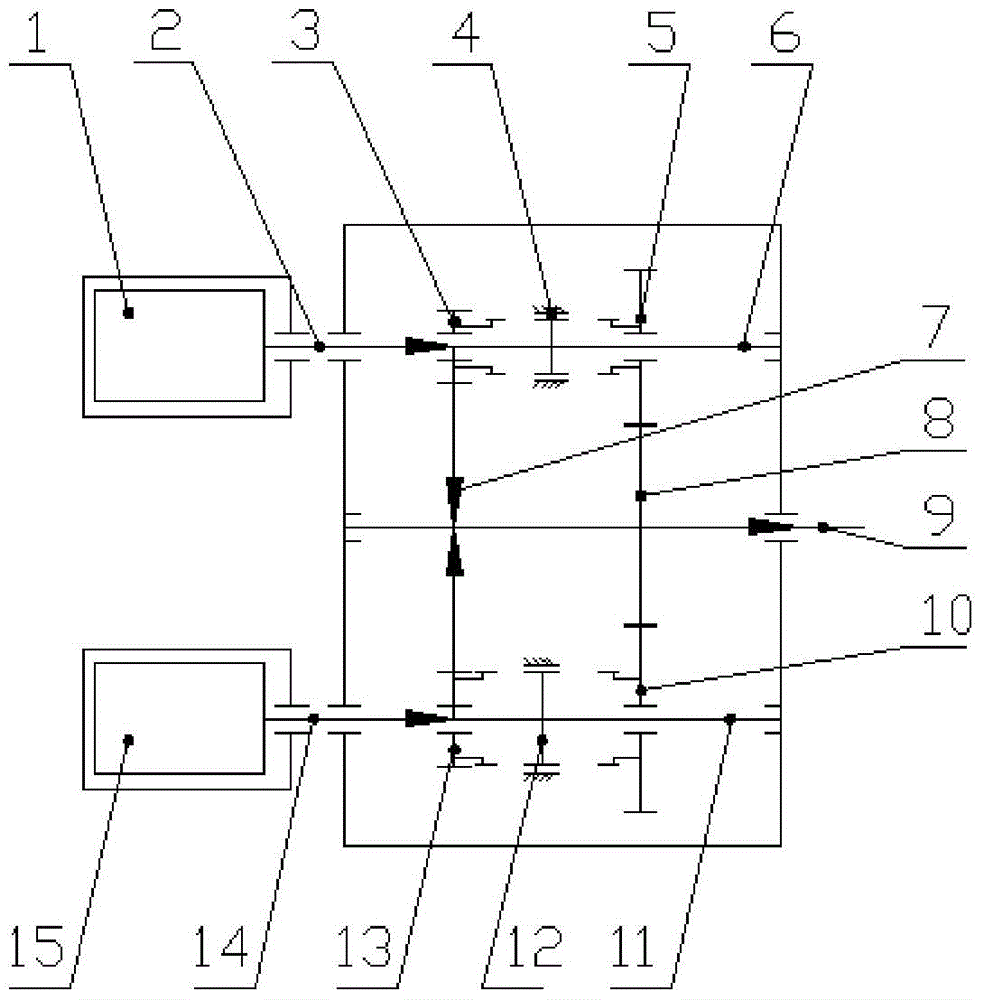
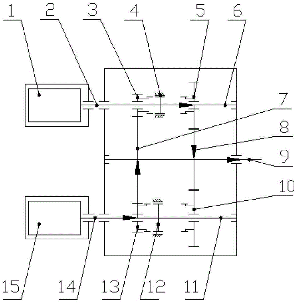
[0049] as attached figure 1 As shown, a vehicle dual-axis parallel electric drive system described in the present invention includes two drive motors and a power output terminal, the drive motors are drive motor I1 and drive motor II15, and the power output terminals are electronically controlled Mechanical automatic transmission. The electronically controlled mechanical automatic transmission of the present invention includes a first gear pair composed of gear I3 meshing with gear III7, a second gear pair composed of gear V13 meshing with gear III7, and a third gear pair composed of gear II5 meshing with gear IV8. gear pair, the fourth-speed gear pair consisting of gear VI10 meshing with gear IV8, adapter sleeve I4, adapter sleeve II12, transmission input shaft I6, transmission input shaft II11, and transmission output shaft III9...


PUM


Abstract

A vehicle biaxial parallel electric drive system and a gear shifting control method thereof. The drive system comprises a drive motor I (1), a drive motor II (15), and an automated mechanical transmission. The automated mechanical transmission comprises a first-gear gear pair (3, 7), a second-gear gear pair (13, 7), a third-gear gear pair (5, 8), a fourth-gear gear pair (10, 8), an engaging sleeve I (4), an engaging sleeve II (12), a transmission input shaft I (6), a transmission input shaft II (11), and a transmission output shaft III (9). The drive system comprises drive motors and an automated mechanical transmission, is simple in structure and reasonably arranged, has high acceleration and gradeability, and implements smooth gear shifting, without any power interruption. By using the gear shifting control method, the continuity of generation of power required for driving can be ensured in a gear shifting process. In addition, kinetic energy ensured during a vehicle traveling process can be converted to electric energy during a braking process, thereby reducing the losses of electric energy, so that the battery costs are reduced and the driving range of the vehicle is improved.

Description

technical field [0001] The invention relates to the technical field of electric vehicle transmission, in particular to a dual-axis parallel electric drive system for a vehicle and a shift control method thereof. Background technique [0002] Environmental protection and energy saving are important issues facing the world in the 21st century. The Chinese government has also proposed the basic national policy of building a conservation-oriented society and the industrial development policy of encouraging the development of small-displacement energy-saving vehicles. Electric vehicles are the way to achieve this goal. One of the important means. [0003] At present, the pure electric drive system widely used in the market includes: multi-speed transmission and traditional drive system with clutch, multi-speed transmission and drive system without clutch, two independent drive motors and fixed gear with drive shaft Transmission device, drive motor and primary reducer transmissio...

Claims


Application Information

Patent Timeline
Patent Type & Authority Patents(China)
IPC IPC(8): B60K17/08B60K17/12B60L15/20
CPCB60K17/08B60K17/12B60L15/20B60K1/02Y02T10/72
Inventor 李占江高超李响李艳会
Owner NANJING YUEBOO POWER SYST CO LTD
Learn More