
Modified treatment system for sludge

A treatment system and modified technology, applied in sludge treatment, water/sludge/sewage treatment, chemical instruments and methods, etc. Sludge and other problems, to achieve the effect of low operating cost, small footprint and easy promotion

Inactive Publication Date: 2016-03-23
湖南省小尹无忌环境能源科技开发有限公司
View PDF8 Cites 2 Cited by
  • Summary
  • Abstract
  • Description
  • Claims
  • Application Information

AI Technical Summary

Problems solved by technology

[0003] In order to make full use of the organic energy in the sludge, improve the fuel performance of the sludge or further improve the combustion performance of the fuel (coal powder), the sludge has to be modified, but so far there has been no research and practice in this area at home and abroad. , and there is no equipment or system that can fully modify sludge to improve sludge combustion performance

Method used


Image

  • Modified treatment system for sludge
  • Modified treatment system for sludge

Examples


Embodiment 1

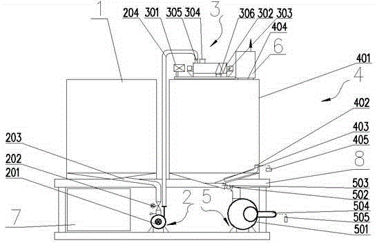
[0023] refer to figure 1 , the present embodiment includes a modified regulator tank 1, a first metering device 2, a mixing device 3, a first modified tank 4, a first cloth feeding device 5, a catalytic oxidation processor 6, an electric control device 7 and Bracket 8, modified modifier tank 1 and mixing and batching device 3 are connected through the first metering and feeding device 2, mixing and batching device 3 is connected with the first modification tank 4, and the first modification tank 4 is respectively connected with the first cloth feeding device 5. The catalytic oxidation processor 6 is connected, and the electric control device 7 is electrically connected with the first metering and feeding device 2, the mixing and batching device 3, the first reforming tank 4, the first cloth feeding device 5, and the catalytic oxidation processor 6, respectively. The modified regulator tank 1, the first metering and feeding device 2, the mixing device 3, the first modifying tan...

Embodiment 2

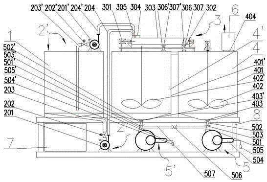
[0030] refer to figure 2, the difference between this embodiment and Embodiment 1 is only that: the first agitator 402 is a mechanical agitator, the first agitator 402 is located in the first tank body 401, and the first air compressor 405 can be omitted; The second feeding device 2', the second modified tank 4' and the second cloth feeding device 5', the second feeding device 2' includes the second feeding pump 201', the third pipeline 203' and the second feeding device 201'. Four pipelines 204', the feed inlet of the second gauge feed pump 201' is connected with the modified regulator tank 1 through the third pipeline 203', the third pipeline 203' is provided with a second pipeline valve 202', the second gauge The discharge port of the feed pump 201' is connected to the compounding device 3 through the fourth pipeline 204'; the second modification tank 4' includes a second tank body 401', a second agitator 402', and the second modification tank 4 ' communicates with the in...


PUM


Abstract

A modified treatment system for sludge comprises a modification conditioner tank, a first dosing and feeding device, a mixing and blending device, a first modification tank, a first distributing and feeding device, a catalytic oxidation processor and an electric control device, wherein the modification conditioner tank and the mixing and blending device are connected through the first dosing and feeding device; the mixing and blending device is connected with the first modification tank; the first modification tank is connected with the first distributing and feeding device and the catalytic oxidation processor respectively; the electric control device is electrically connected with the first dosing and feeding device, the mixing and blending device, the first modification tank, the first distributing and feeding device and the catalytic oxidation processor respectively. The modified treatment system is capable of effectively realizing modified treatment of sludge, is conductive to realizing resource and energy utilization of sludge at a large amount and a large area and is free of secondary pollution; the modified treatment system is simple and compact in structure, few in occupied area, relatively low in cost, simple to use, energy-saving, low in running cost and convenient to promote.

Description

technical field [0001] The invention relates to a sludge modification treatment system. Background technique [0002] In the process of sludge resource utilization and energy utilization, because the sludge contains a large amount of water, slime and harmful substances, there is a possibility of causing secondary sludge hazards. At the same time, the muddy inorganic substances in the sludge also objectively affect the combustion performance. [0003] In order to make full use of the organic energy in the sludge, improve the fuel performance of the sludge or further improve the combustion performance of the fuel (coal powder), the sludge has to be modified, but so far there has been no research and practice in this area at home and abroad. , and there is no equipment or system that can fully modify sludge to improve sludge combustion performance. Contents of the invention [0004] The technical problem to be solved by the present invention is to overcome the deficiencies ...

Claims


Application Information

Patent Timeline
IPC IPC(8): C02F11/00
CPCC02F11/00
Inventor 尹无忌尹小林
Owner 湖南省小尹无忌环境能源科技开发有限公司
Learn More