House interlayer cast-in-situ cavity floor

A cavity floor and interlayer technology, applied in the direction of floors, building components, buildings, etc.

Inactive Publication Date: 2016-03-23
王本淼 +2
View PDF6 Cites 28 Cited by
  • Summary
  • Abstract
  • Description
  • Claims
  • Application Information

AI Technical Summary

Problems solved by technology

[0004] The object of the present invention is to use a shear wall or a wall instead of a beam for a house interlayer cast-in-place cavity floor, make full use of the combination of light steel beams and reinforced concrete, combine the film effect and surface tension of cast-in-place concrete, and use unsealed The ribbed steel mesh hollowing realizes the hole-forming technology of the cast-in-place cavity floor slab to reduce the height of the light steel beam and occupy less limited space; On the inner surface, a convex cement mortar pile group is formed to hold the steel mesh body together to resist cracking; the development and production efficiency is high, the composite property with concrete is good, the isolation and fixation are eliminated, and the addition of anti-cracking steel wire mesh is eliminated, the quality is improved, and the construction is reduced Auxiliary cost, convenient transportation and construction, no buoyancy, inhibiting the generation of building cracks, meeting the design requirements, and ensuring the quality of the ribbed steel mesh are the key points; Mesh metal material overcomes the defect that any filling body in the existing hollow floor slab hole forming technology cannot work together with the floor to bear the force; it can reduce the hidden dangers of quality and safety caused by the inconsistent standards of the interlayer of the house and the durability of the interlayer and the main body of the building. coexist

Method used


Image

  • House interlayer cast-in-situ cavity floor
  • House interlayer cast-in-situ cavity floor

Examples


Embodiment Construction

[0012] The present invention will be further described below in conjunction with the accompanying drawings.

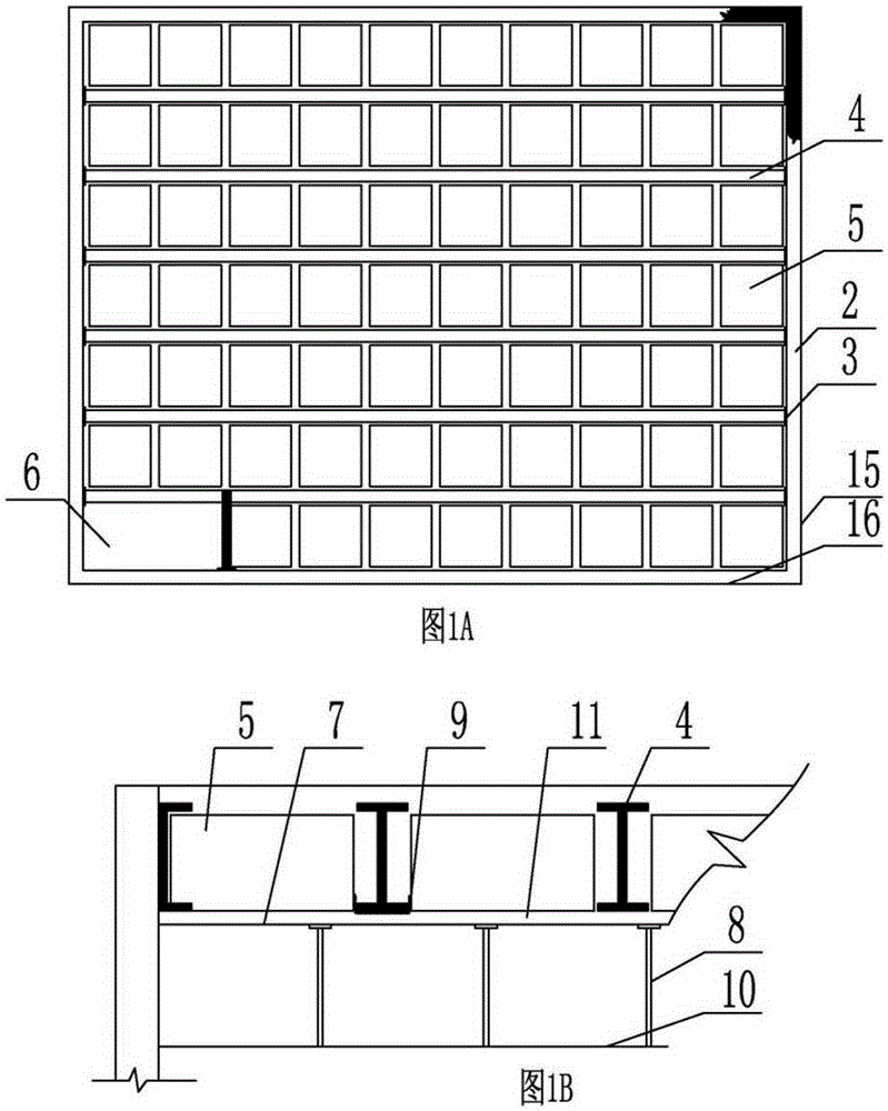
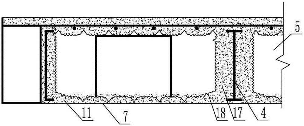
[0013] figure 1 It is a structural drawing of a cast-in-situ cavity floor slab of a house interlayer according to the present invention; figure 1 Decomposed into figure 1 A is the floor plan, figure 1 B is a sectional view. When the present invention is implemented, the position of adding another layer of mezzanine floor slabs is determined in the middle of the height of the interlayer space reserved for the main house building, and the shear wall 2 or the wall 2 at this position is used to generate the main beam, and in X The composite member 3 is installed on the wall of the axis or Y-axis; the support rod 8 of the sandwich formwork 7 is erected on the fixed floor 10; the stairway 6 is reserved, and the light steel beam 4 used for the sandwich floor is welded on the wall to install the composite member 3 to form Beam 4 of the mezzanine floor; in order to reduce th...


PUM

PropertyMeasurementUnit
thicknessaaaaaaaaaa
thicknessaaaaaaaaaa

Abstract

The invention provides a house interlayer cast-in-situ cavity floor. The house interlayer cast-in-situ cavity floor comprises interlayer space height reserved in a main body house building, light steel beams, a light steel beam and wall slab combined member, a reinforced concrete upper flange slab, a hollow ribbed steel mesh and a lower flange thin slab compounded with concrete mortar at the bottom of the hollow ribbed steel mesh, wherein a house interlayer cast-in-situ cavity floor is arranged in the reserved space height of the main body building; the house interlayer cast-in-situ cavity floor adopts light steel beams; the compounded lower flange thin slab is directly compounded by cement mortar and the bottom surface of the hollow ribbed steel mesh; the thickness of the lower flange thin slab is smaller than or equal to 30mm; the hollow ribbed steel mesh comprises a hollow mesh, a floor end mesh and a support mesh; the thickness of the interlayer cast-in-situ cavity floor is smaller than or equal to 250mm. Through the house interlayer cast-in-situ cavity floor, the defect that any filling body cannot act and stress with the floor of the existing cavity floor hole formation technique is overcome; the potential safety hazard of the quality caused by non-uniform house interlayer standard is reduced; the interlayer durability co-exists with the building main body.

Description

technical field [0001] The invention relates to a technology for adding layers of structural layers of a main building, in particular to a technology for cast-in-place cavity floor slabs for house interlayers. Background technique [0002] At present, real estate developers put forward the business concept of buying one floor and getting one floor free. In fact, when real estate developers develop real estate, the height of the main building structure is greater than that of ordinary buildings, and the floor height purchased by the landlord is greater than the market floor and less than that of the market. After two floors of space, in order to make full use of the space, the landlord usually builds another floor with a different building structure, so as to realize the developer's concept of buying one floor for one floor; obviously the thickness of the rebuilt floor directly affects the two floors. The space height and construction methods are also varied, and the construc...

Claims


Application Information

Patent Timeline
Patent Type & Authority Applications(China)
IPC IPC(8): E04B5/36
CPCE04B5/36
Inventor 王海崴王本淼马锋杨建军
Owner 王本淼
Why Eureka
Try Eureka