Structure of compensation filter device in multi-sequence laser shadow photography

A technology for compensating filter devices and laser shadows. It is applied to filters, cameras, installations, etc. for photographic purposes. Satisfy the effect of normal sensitivity

Active Publication Date: 2018-08-10
中国空气动力研究与发展中心超高速空气动力研究所
View PDF7 Cites 0 Cited by
  • Summary
  • Abstract
  • Description
  • Claims
  • Application Information

AI Technical Summary

Problems solved by technology

[0005] Since ultra-high-speed phenomena are often accompanied by strong self-illumination, these self-luminescence will interfere with the information of the test target, and placing a narrow-band filter for stray light filtering will produce undesired fringes in the optical path. It will also make the beam uneven and affect the imaging quality
In order to eliminate stray light and not affect the imaging quality, a compensation filter device is used in the imaging system of the camera system, but because the compensation filter device involves a variety of optical components, and the compensation filter device needs to be repeatedly checked before each use Debugging, it is often difficult to fix after the debugging is in place, and it needs to be continuously debugged in the next use

Method used


Image

  • Structure of compensation filter device in multi-sequence laser shadow photography
  • Structure of compensation filter device in multi-sequence laser shadow photography

Examples


Embodiment Construction

[0019] The specific embodiment of the present invention is described in further detail below in conjunction with accompanying drawing:

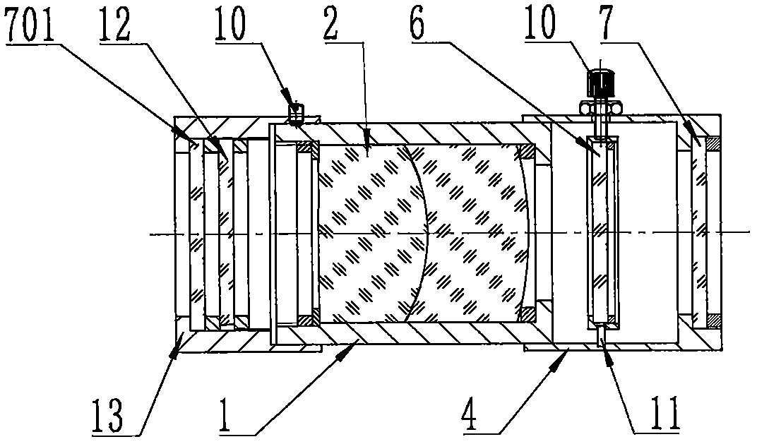
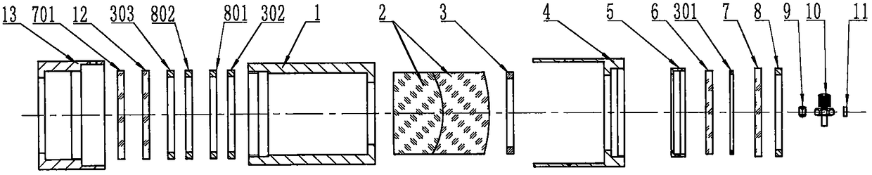
[0020] A compensation filter device structure in multi-sequence laser shadow photography, such as figure 1 and figure 2 As shown, it includes a main body sleeve 1, an imaging objective lens 2, a first gasket 3, a filter adjusting cylinder 4, a filter fixing cylinder 5, a filter 6, a second gasket 301, a first protective window glass 7, a second A pressure ring 8, a limit nail 9, a locking screw 10, a limit rod 11, a third washer 302, a second pressure ring 801, a third pressure ring 802, a fourth washer 303, a density gradient filter 12, the first Two protective window glass 701 and density gradient filter adjustment cylinder 13;

[0021] The front and rear ends of the main body sleeve 1 are respectively placed with the first protective window glass 7 and the second protective window glass 701, and the second protective window glass 701 an...


PUM


Abstract

The invention belongs to the field of ultra-high-speed transient imaging, and relates to a structure of a compensation filter device in multi-sequence laser shadow photography, including a main body sleeve, an imaging objective lens, a first gasket, an optical filter adjusting cylinder, an optical filter fixing cylinder, Filter, second washer, first protective window glass, first pressure ring, limit nail, locking screw, limit rod, third washer, second pressure ring, second pressure ring, fourth washer, density Graduated Filter, Second Protection Window Glass and Density Graduated Filter Adjustment Barrel. The present invention places protective window glass at the front and back ends of the compensation filter device, which can prevent dust from entering the surface of the optical element and the surface of the moisture-proof optical element from being damp; match.

Description

technical field [0001] The invention belongs to the field of ultra-high-speed transient imaging, and relates to a compensation filter device structure in multi-sequence laser shadow photography. Background technique [0002] With the development of my country's aerospace technology, weapons and equipment, and basic disciplines, research in the fields of ultra-high-speed aerodynamics, ultra-high-speed collisions, explosions and impacts, combustion and chemical reactions has continued to deepen. In these research works, many phenomena are ultra-high-speed transient change processes with a duration of only microseconds or even nanoseconds. It is necessary to have a camera system that can clearly and continuously image and record this process in order to grasp the physical phenomena. Nature. In addition to requiring the amplitude and frequency to reach 10 million frames per second (that is, the shortest exposure and imaging time is 100ns), this camera system can perform sequent...

Claims


Application Information

Patent Timeline
Patent Type & Authority Patents(China)
IPC IPC(8): G03B39/00G03B11/00G02B26/02G02B7/00
CPCG02B7/006G02B26/023G03B11/00G03B39/00
Inventor 谢爱民黄洁宋强文雪忠柯发伟李晶柳森
Owner 中国空气动力研究与发展中心超高速空气动力研究所
Why Eureka
Try Eureka