
Genetic algorithm-based MIMO-SAR planar array antenna array element position optimization method

A technology of MIMO-SAR and genetic algorithm, which is applied in the field of multi-input multi-output synthetic aperture radar imaging and radar, can solve the problems of monotonous genetic algorithm population, optimization problems that cannot reach the optimal solution, premature convergence, etc.

Active Publication Date: 2016-03-23
UNIV OF ELECTRONIC SCI & TECH OF CHINA
View PDF4 Cites 29 Cited by
  • Summary
  • Abstract
  • Description
  • Claims
  • Application Information

AI Technical Summary

Problems solved by technology

By changing the positions of the antenna transmitting and receiving elements in the array, suppressing the side lobe level of the equivalent transmitting and receiving antenna pattern and reducing the width of the main lobe as much as possible, the purpose of optimizing the array is achieved; in the selection of the optimization method, the genetic algorithm It is very suitable for nonlinear optimization problems, so a lot of research has been done to solve the optimization problem of sparse one-dimensional linear arrays. However, the genetic algorithm may produce population monotony and premature convergence, making the optimization problem unable to reach the optimum. untie

Method used


Image

  • Genetic algorithm-based MIMO-SAR planar array antenna array element position optimization method
  • Genetic algorithm-based MIMO-SAR planar array antenna array element position optimization method
  • Genetic algorithm-based MIMO-SAR planar array antenna array element position optimization method

Examples


Embodiment Construction

[0079] The present invention mainly adopts the method of simulation experiment for verification, and all steps and conclusions are verified correctly on MATLAB2013a. The specific implementation steps are as follows:

[0080] Step 1. MIMO-SAR area array parameter initialization:

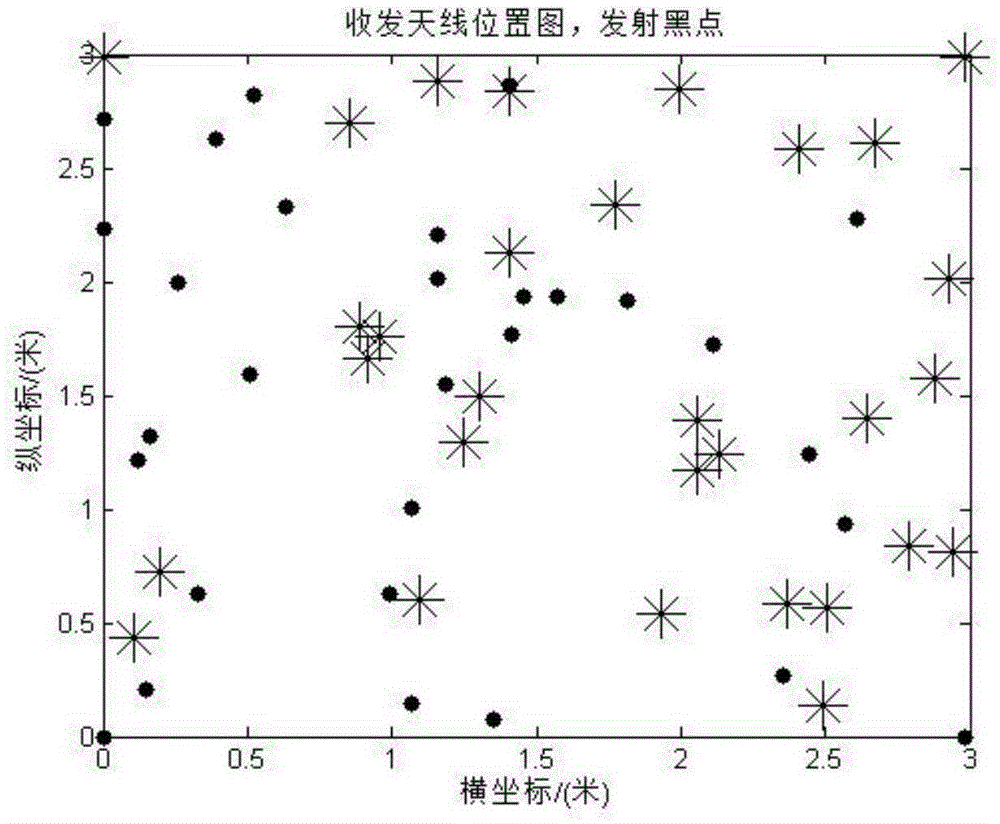
[0081] Initialize the MIMO-SAR area array parameters include: the carrier wavelength λ=0.03m of the radar transmitting signal; the propagation speed of the electromagnetic wave in the air, denoted as C=3×10 8 Hz; the minimum interval between array elements, dc=0.015m; the number of transmitting array elements, TN=30; the number of receiving array elements, RN=30; the total number of array elements, SN=60; the pitch angle of the target scattering point, θ 0 = 45 degrees; the azimuth angle of the target scattering point, According to the multiple-input multiple-output synthetic aperture radar imaging system scheme, the initialization parameters of the MIMO-SAR array are all known.

[0082] Step 2. G...


PUM


Abstract

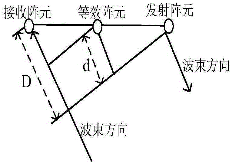
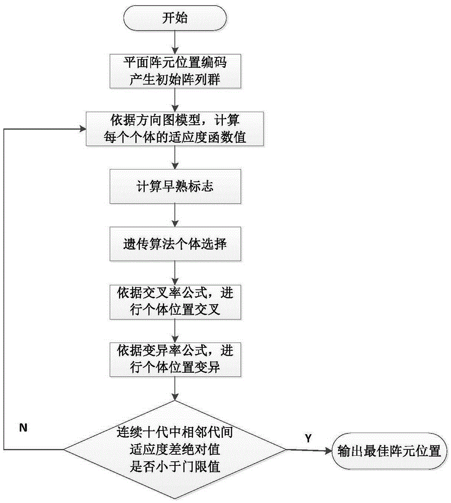
The invention provides a genetic algorithm-based MIMO-SAR planar array antenna array element position optimization method. According to the method, an array directional diagram optimization model is established on the basis of an antenna phase center approximation principle; array element positions are selected on grid points in the encoding process of a genetic algorithm by taking the minimum peak side lobe ratio and the minimum main lobe width as optimization objectives; two transmission array elements and two reception array elements are laid at four end points of a laying area to ensure the maximum length of the array; the early-maturing of the genetic algorithm is inhibited to obtain the optimal array element positions; by adopting the planar array form constrained by the array element minimum distance, the number of the required array elements is greatly decreased, so that the cost and calculated amount of an antenna system are effectively reduced, the method is more suitable for the engineering design, and convenience is provided for the MIMO-SAR three-dimensional imaging and objective detection and recognition.

Description

Technical field: [0001] The invention belongs to the technical field of radar, and in particular relates to the technical field of multiple-input multiple-output synthetic aperture radar (MIMO-SAR) imaging. Background technique: [0002] With the in-depth research on MIMO (multi-input multi-output) radar, people put forward the concept of MIMO-SAR, that is, "put the coherent MIMO radar on the moving platform, and comprehensively use the echo data of all the transmitting and receiving combinations to perform coherent imaging, defined as MIMO-SAR". It transmits multiple uncorrelated waveforms independently at the same time through multiple antennas at the transmitting end, and multiple antennas at the receiving end independently receive scene echoes at the same time, which can equivalently produce more observation channels, thereby reducing the number of actual antenna elements. The application of MIMO radar technology to SAR system provides a new way for high-resolution imag...

Claims


Application Information

Patent Timeline
IPC IPC(8): G06F17/50
CPCG06F30/20G01S13/90
Inventor 张晓玲余鹏范小天郭立文
Owner UNIV OF ELECTRONIC SCI & TECH OF CHINA
Learn More