Relativistic magnetron for realizing frequency hopping operation by utilizing transparent negative electrode

A technology of relativistic magnetrons and transparent cathodes, applied in the field of relativistic magnetrons, can solve the problems of slow frequency adjustment time of tunable relativistic magnetrons, difficult adjustment of relativistic magnetrons with permanent magnet packaging, frequency agility, inconvenience, etc.

Inactive Publication Date: 2016-03-23
UNIV OF ELECTRONICS SCI & TECH OF CHINA
View PDF10 Cites 13 Cited by
  • Summary
  • Abstract
  • Description
  • Claims
  • Application Information

AI Technical Summary

Problems solved by technology

[0004] The purpose of the present invention is to provide a relativistic magnetron with fast frequency conversion, which aims to solve the problem of slow and inconvenient frequency adjustment time of traditional tunable relativistic magnetrons, and is also aimed at working with relativistic magnetrons such as permanent magnet packages. Frequency agility where magnetic field or operating voltage regulation is difficult

Method used


Image

  • Relativistic magnetron for realizing frequency hopping operation by utilizing transparent negative electrode
  • Relativistic magnetron for realizing frequency hopping operation by utilizing transparent negative electrode
  • Relativistic magnetron for realizing frequency hopping operation by utilizing transparent negative electrode

Examples


Embodiment Construction

[0029] In order to make the object, technical solution and advantages of the present invention more clear, the present invention will be further described in detail below in conjunction with the examples. It should be understood that the specific embodiments described here are only used to explain the present invention, not to limit the present invention.

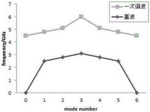
[0030] The operating frequency points of the frequency-hopping relativistic magnetron of the embodiment of the present invention are respectively 2.90GHz (π mode, S band) and 4.20GHz (2π mode, C band), and the output power is about 700MW, requiring the relativistic magnetron operating frequency to jump When changing, the working electrical parameters remain constant.

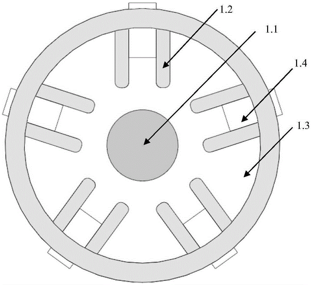
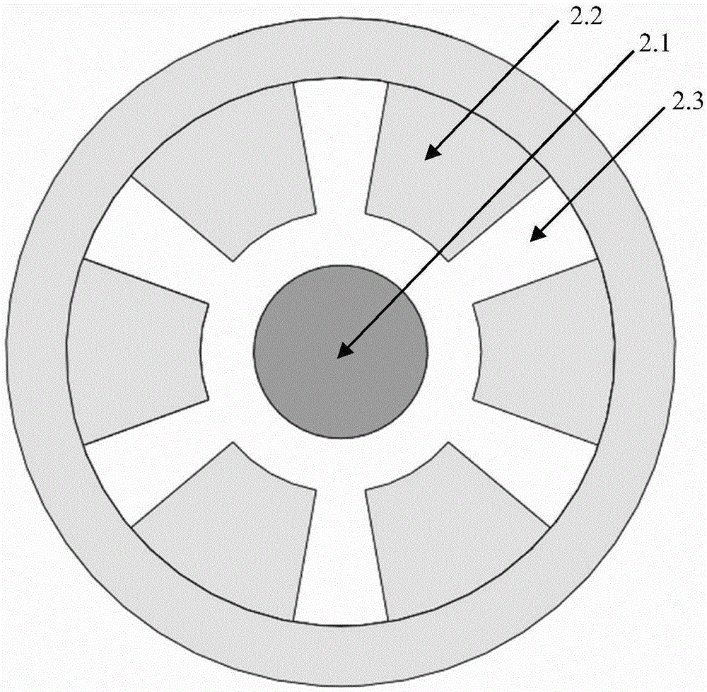
[0031] This example image 3 As shown, a relativistic magnetron that uses a transparent cathode to realize frequency hopping work works under vacuum conditions and includes a shell 6, an anode 2 with a same cavity structure, a magnetron resonant cavity 3, an...


PUM


Abstract

The invention discloses a relativistic magnetron for realizing a frequency hopping operation by utilizing a transparent negative electrode, and belongs to the technical field of electronic countermeasure. The relativistic magnetron comprises a shell, a co-cavity structured positive electrode, a magnetron resonant cavity, the transparent negative electrode consisting of a plurality of sector negative electrodes, a tuning unit and an energy coupling output apparatus. According to the relativistic magnetron, the conventional columnar negative electrode is designed into the sector transparent negative electrode; the mode conversion between a pi mode and a 2pi mode is realized by changing the relative angle between the negative electrode fan-shaped emitting surface and the fan-shaped resonant cavity; when the relative angle between the negative electrode emitting surface and the fan-shaped resonant cavity is changed, the static electric field distribution between the negative electrode and the positive electrode is changed accordingly; meanwhile, the initial phase position of an electron beam relative to a resonant mode high frequency field is affected as well; therefore, when the negative electrode is rotates, the working mode of the relativistic magnetron is changed along with the change of the relative angle between the negative electrode emitting surface and the fan-shaped resonant cavity so as to fulfill the purpose of changing the frequency agility.

Description

technical field [0001] The invention belongs to the technical field of electronic countermeasures, and in particular relates to a relativistic magnetron with frequency hopping operation. Background technique [0002] Relativistic magnetron is one of the representative high-power microwave sources. It has the characteristics of simple structure, durable skin and high repetition frequency operation. It is widely used in various high-power microwave systems, such as Orion in the United Kingdom and MTF in Sweden. , France's Hyperion, Germany's Supra and other system-level high-power microwave effect systems all use or partially use tunable relativistic magnetrons. In recent years, with the continuous deepening of research on high-power microwave effects and the requirements of practical application, a fast and tunable relativistic magnetron, that is, the frequency-agile technology of relativistic magnetron, has been proposed. It is required that the relativistic magnetron has a...

Claims


Application Information

Patent Timeline
Patent Type & Authority Applications(China)
IPC IPC(8): H01J25/50H01J23/04
CPCH01J25/50H01J23/04
Inventor 李天明胡标李浩汪海洋
Owner UNIV OF ELECTRONICS SCI & TECH OF CHINA
Why Eureka
Try Eureka