
Air mass flow meter

A technology of air mass flow and sensor element, which is applied in the direction of measuring flow/mass flow, volume flow ratio measurement, testing/calibrating volume flow, etc., which can solve the problems of air mass flow measurement distortion and other issues

Active Publication Date: 2016-03-23
VTESCO TECH GMBH
View PDF6 Cites 0 Cited by
  • Summary
  • Abstract
  • Description
  • Claims
  • Application Information

AI Technical Summary

Problems solved by technology

However, precisely this pulsation can lead to a significant distortion of the measured value of the average air mass flow

Method used


Image

  • Air mass flow meter
  • Air mass flow meter
  • Air mass flow meter

Examples


Embodiment Construction

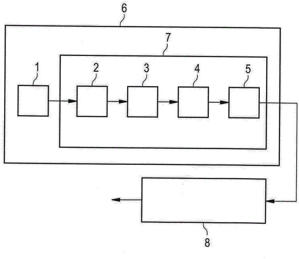
[0024] figure 1 A combustion engine 11 is shown. The combustion engine 11 may be not only a combustion engine 11 driven with gasoline, but also a combustion engine 11 driven with diesel fuel. It is also conceivable for the combustion engine 11 to be driven with gas. An intake pipe 14 can be seen on the combustion engine 11 , which is connected to an air filter 15 . External air is sucked into the intake manifold 14 via the air filter 15 and supplied to the combustion engine 11 . For optimum combustion of the fuel it is necessary to precisely determine the air mass flow Q delivered in the intake manifold 14 . This determination of the air mass flow Q takes place via the air mass flow meter 6 , which forwards its signal S to the engine control unit 8 . Engine control unit 8 controls, for example, injection pump 13 and nozzles 12 as a function of signal S provided by air mass flow meter 6 . In this way, a precisely metered quantity of fuel is delivered to each cylinder 16 of...


PUM


Abstract

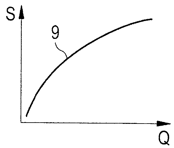
The invention relates to an air mass flow meter, comprising a sensor element for detecting an air mass flow and for producing a signal and comprising an electronic circuit for processing the signal from the sensor element, wherein the sensor element produces a non-linear signal characteristic. In order to specify a rapid air mass flow meter that has as small an error as possible in the processing of the signal, the electronic circuit (7) first has an element (2) for converting the non-linear signal characteristic (9) from the sensor element (1) into a correcting signal characteristic (10) that is non-linear at least in some segments, and the circuit then has a filter element (3), a conversion element (4) for converting the correcting signal characteristic (10) which is non-linear at least in some segments into a non-linear signal characteristic (9), and a relay element (5) for relaying the signals (S) detected by the sensor element (1) and processed by the linearization element (2), the filter element (3), and the conversion element (4).

Description

technical field [0001] The invention relates to an air mass flowmeter having: a sensor element for detecting the air mass flow and for generating a signal; and an electronic circuit for processing the signal of the sensor element, wherein the sensor element generates a non-linear signal characteristic curve. Furthermore, the invention relates to a method for processing signals of an air mass flow meter, wherein the air mass flow meter has a sensor element for detecting the air mass flow and for generating a signal, and has a sensor element for processing the sensor The electronic circuit of the signal of the element, wherein the sensor element generates a non-linear signal characteristic curve. Background technique [0002] The air mass flow meter is suitable for detecting the flow rate of a fluid (air mass flow rate) in a flow channel. Such a flow channel can be, for example, an intake manifold of an internal combustion engine. Depending on the mass flow detected by the ...

Claims


Application Information

Patent Timeline
Patent Type & Authority Applications(China)
IPC IPC(8): G01F25/00G01F1/684G01F1/696
CPCG01F1/6845G01F1/6965G01F25/10G01F1/688G01F1/696G01F1/684F02D41/187G01F5/00G01F1/698G01F1/6842
Inventor S.许雷尔T.克尼特尔S.塞特斯卡克
Owner VTESCO TECH GMBH
Learn More