Method for manufacturing liquid-crystal display

A technology of a liquid crystal display device and a manufacturing method, applied in optics, instruments, nonlinear optics, etc., can solve problems such as damage to thin-film transistor elements, uneven display, poor foreign matter, etc., and achieve the effect of improving display quality

Inactive Publication Date: 2016-03-23
SHARP KK
View PDF9 Cites 4 Cited by
  • Summary
  • Abstract
  • Description
  • Claims
  • Application Information

AI Technical Summary

Problems solved by technology

However, when the rubbing method is used, there are problems such as foreign matter defects and display unevenness caused by dust generated by the cloth, and destruction of the thin film transistor element caused by static electricity when rubbed with the cloth.
In addition, with the development of high-definition tablet PCs and smartphones, it is difficult to align liquid crystal molecules uniformly in the rubbing method in which the accuracy of the orientation treatment is limited by the density of the wool of the cloth.

Method used


Image

  • Method for manufacturing liquid-crystal display
  • Method for manufacturing liquid-crystal display
  • Method for manufacturing liquid-crystal display

Examples


Embodiment 1

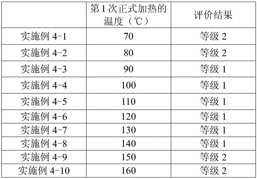
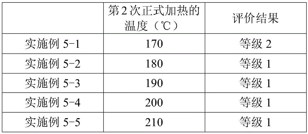
[0052] In Example 1, the main heating is performed twice at different temperatures in the above step (4), and between the first main heating (first main heating step) and the second main heating (second main heating step), Furthermore, when light irradiation (2nd light irradiation process) is performed to the said film which performed the 1st main heating. Hereinafter, the method of manufacturing the liquid crystal display device of Example 1 will be sequentially described.

[0053] (Structure of liquid crystal display device)

[0054] It is a liquid crystal display device with an electrode structure for the FFS mode, and the pretilt angle is 0°.

[0055] (Photo Alignment Film Material)

[0056] As the solid content, a polymer having a methacryloyl skeleton and containing a photoreactive cinnamate group in a side chain is used. As the solvent, a solvent obtained by mixing N-methyl-pyrrolidone and butyl cellosolve at a weight ratio of 50:50 was used. In addition, the solid content c...

Embodiment 2

[0091] Example 2 is a case where a liquid crystal material containing liquid crystal molecules having negative dielectric constant anisotropy is used in Example 1. The manufacturing method of the liquid crystal display device of Example 2 is the same as that of Example 1 except that the dielectric constant anisotropy of the liquid crystal molecules is different. Therefore, the description of the overlapping points is omitted.
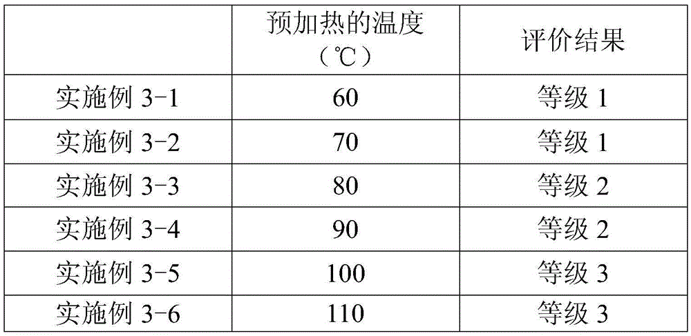
Embodiment 3-1

[0117] In Example 3-1, the main heating was performed twice at different temperatures in the above step (4). The method of manufacturing the liquid crystal display device of Example 3-1 will be sequentially described below.

[0118] (Structure of liquid crystal display device)

[0119] It is a liquid crystal display device with an electrode structure for the FFS mode, and the pretilt angle is 0°.

[0120] (Photo Alignment Film Material)

[0121] As the solid content, a polymer containing an azobenzene structure having photoreactivity is used. As the solvent, a solvent obtained by mixing N-methyl-pyrrolidone and butyl cellosolve at a weight ratio of 50:50 was used. In addition, the solid content concentration was 4% by weight. Here, the azophenyl group is a photofunctional group capable of photoisomerization.

[0122] (Process of forming a film of photo-alignment film material)

[0123] On two substrates, a film of a photo-alignment film material was formed by a spin coating method.

...


PUM

PropertyMeasurementUnit
thicknessaaaaaaaaaa

Abstract

This invention provides a method for manufacturing a liquid-crystal display that contains a photo-alignment film and can substantially improve display quality. Said method for manufacturing a liquid-crystal display containing a photo-alignment film has the following steps, in this order: a step (1) in which a film of a photo-alignment-film material is formed on a substrate, said photo-alignment-film material containing a solvent and a polymer that has an optical functional group that can undergo at least one chemical reaction selected from the group consisting of photodimerization, photoisomerization, and optical Fries rearrangement; a step (2) in which the aforementioned film is subjected to preliminary heating that vaporizes the aforementioned solvent; a step (3) in which the film, having been subjected to preliminary heating, is exposed to polarized light; and a step (4) that includes an operation in which the film, having been exposed to polarized light, is subjected to a primary heating process at a plurality of temperatures from low to high. This liquid-crystal display is a fringe-field-switching-mode liquid-crystal display or an in-plane-switching-mode liquid-crystal display with a pretilt angle that is effectively 0 DEG.

Description

Technical field [0001] The present invention relates to a method of manufacturing a liquid crystal display device. More specifically, it relates to a method of manufacturing a liquid crystal display device regarding the formation conditions of the alignment film. Background technique [0002] In recent years, thin display devices such as liquid crystal display devices have spread rapidly, not only for televisions, but also for e-books, photo frames, IA (Industrial Appliance), PC (Personal Computer), tablet PCs, smartphones, etc. Is widely adopted. In these applications, various performances are required, and various liquid crystal display modes have been developed. [0003] As a liquid crystal display mode commonly used in recent years, an in-plane switching (In-Plane Switching: IPS) mode in which liquid crystal molecules with positive or negative dielectric anisotropy are aligned in a direction parallel to the main surface of the substrate can be cited And FringeFieldSwitching ...

Claims


Application Information

Patent Timeline
Patent Type & Authority Applications(China)
IPC IPC(8): G02F1/1337C08L101/02
CPCG02F1/134363G02F1/133788G02F1/134372G02F1/133711
Inventor 三宅敢宫地弘一浅木大明
Owner SHARP KK
Why Eureka
Try Eureka