Efficiency damped and sealed vertical mill

A vertical grinding and high-efficiency technology, which is applied to the sealing of the engine, mechanical equipment, engine components, etc., can solve the problems of reduced output of the mill, malfunction of the main shaft, and high maintenance rate, so as to ensure the sealing performance and reduce the maintenance rate. , the effect of high system stability

Active Publication Date: 2016-03-30
HENAN LIMING HEAVY IND SCI & TECH +1
View PDF15 Cites 4 Cited by
  • Summary
  • Abstract
  • Description
  • Claims
  • Application Information

AI Technical Summary

Problems solved by technology

Due to the harsh working conditions of the pulverizer, a large amount of dust will be generated. Although the above two structures use shaft sealing devices to prevent dust from entering the interior of the suspension swing device during work, from the current use situation, the two structures are different. There is still a phenomenon of powder entering the suspension and swing device of the mill, and the entering dust is mixed with the internal lubricating grease to form sludge. When the sludge reaches a certain amount, it will still tightly hug the main shaft, causing the main shaft to run The phenomenon of failure causes high maintenance rate, and it is difficult to disassemble during maintenance, which increases the maintenance time, makes the user unable to continue production, reduces the output of the mill per unit time, and cannot reach the designed output of the mill
At the same time, due to the severe vibration and high noise when the mill is working, although the shock absorbing device is designed, there is still room for improvement

Method used


Image

  • Efficiency damped and sealed vertical mill
  • Efficiency damped and sealed vertical mill
  • Efficiency damped and sealed vertical mill

Examples


Embodiment Construction

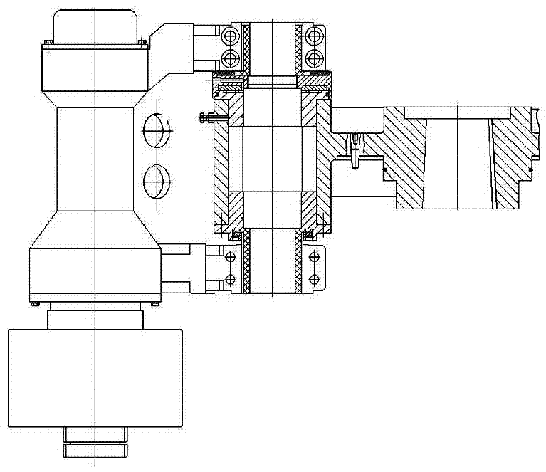
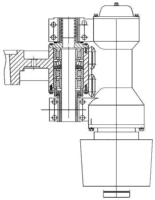
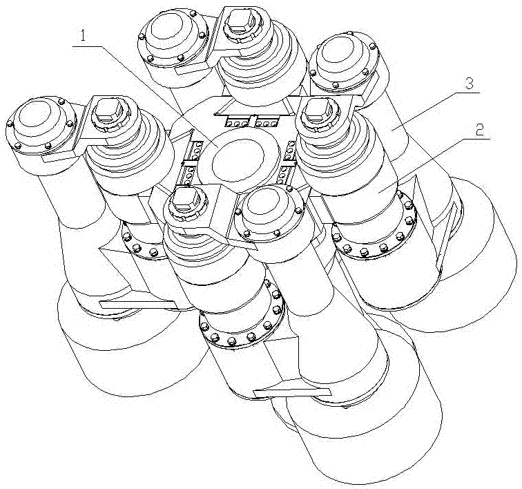
[0020] like image 3 , 4 , 4-1, the high-efficiency shock-absorbing and sealed vertical mill of the present invention includes a plum blossom frame 1 placed in the body and a device that is evenly arranged on the plum blossom frame and is driven by a swing arm mechanism 2 suspended by the plum blossom frame. The grinding roller assembly 3, the suspension swing arm mechanism 2 of the present invention includes a vertical shaft 2.1 arranged in the longitudinal through hole of the plum blossom frame dovetail groove plate 4, a rotating assembly with a shaft sealing device is arranged on the vertical shaft 2.1, and the top of the vertical shaft 2.1 A gravity support device connected to the grinding roller assembly 3 is provided;

[0021] The rotating assembly adopted in the present invention includes an upper bearing 2.2 and a lower bearing 2.3 set in the lower bearing chamber of the vertical shaft 2.1, a wear-resistant sleeve 2.4 is arranged between the upper bearing 2.2 and the ...


PUM


Abstract

The invention discloses an efficiency damped and sealed vertical mill. The efficiency damped and sealed vertical mill comprises a star rack and a mill roller assembly, wherein the mill roller assembly works under the driving action of a suspension swing arm mechanism; the suspension swing arm mechanism comprises a vertical shaft arranged in a through hole of a dovetail slotted disc, a gravity support device connected with the mill roller assembly is arranged at the top of the vertical shaft, and a rotating assembly is arranged on the vertical shaft; the rotating assembly comprises an upper bearing arranged in a bearing cavity at the lower part of the vertical shaft in a sleeving manner, a wear-resistant sleeve and a lower bearing, and the inner hole wall of an upper bearing gland buckled on the upper bearing extends upwards along the vertical shaft so as to form a jacket; and the bottom of the dovetail slotted disc of the star rack is fixedly connected with a seal sleeve, and the seal sleeve extends downwards and is wrapped outside the jacket; and upper and lower oil seals and upper and lower seal steel discs are arranged in an annular cavity formed between the inner wall of the seal sleeve and the outer wall of the jacket, and a grease seal cavity is formed between the upper and lower oil seals. The efficiency damped and sealed vertical mill can ensure the high tightness of a bearing housing, is high in system stability, is low in maintenance rate, and can realize continuous production for users. Compared with the same class of machines, the efficiency damped and sealed vertical mill can increase the yield by 30%.

Description

technical field [0001] The invention relates to a pulverizer, in particular to a high-efficiency shock-absorbing and sealed vertical pulverizer. Background technique [0002] When the vertical mill is working, the plum blossom frame rotates, and the grinding roller assembly driven by the suspension device swings longitudinally with the vertical shaft of the suspension device as the center of the circle under the action of centrifugal force, that is, the vertical shaft does not move, and the grinding roller assembly rotates relative to the vertical shaft. Ensure that the grinding roller is always in close contact with the grinding ring, and grind the material between the grinding roller and the grinding ring into powder. The suspension and swing device of the existing grinding roller assembly of the vertical mill produced by our company has two structures: one is as figure 1 As shown, ring oil grooves are provided on the inner hole walls of the upper and lower wear-resistant...

Claims


Application Information

Patent Timeline
Patent Type & Authority Applications(China)
IPC IPC(8): B02C15/08F16J15/16F16F15/08
CPCB02C15/08F16F15/08F16J15/16
Inventor 刘晓锋宁晋
Owner HENAN LIMING HEAVY IND SCI & TECH
Why Eureka
Try Eureka