Precision forming method for straight/helical tooth cylinder gear with corners easy to fill and die

A technology of precision forming and corners, applied in the direction of wheels, manufacturing tools, forging/pressing/hammer devices, etc., can solve the problems of high manufacturing cost, inconvenient practical application, and large stress ball tensor

Inactive Publication Date: 2016-03-30
NANCHANG UNIV
View PDF9 Cites 11 Cited by
  • Summary
  • Abstract
  • Description
  • Claims
  • Application Information

AI Technical Summary

Problems solved by technology

The traditional mainstream method has several disadvantages: one is that the streamline of the forging structure is cut off, which reduces the mechanical properties of the gear teeth; the other is that the cutting process occupies a large number of equipment and consumes a lot of man-hours, the number of workpiece turnovers is large, and the production cycle (process) is long. Low efficiency; the third is low material utilization, high energy consumption, and high manufacturing costs
The disadvantage of this method is that since the billet forms a rigid area after upsetting, the tensor of the stress ball is very large, and it needs to apply a huge force to squeeze its central part. In the case of a large rim width, it is difficult to ensure the At the same time, the number of blocks in the mold cavity increases, and relative movement between the blocks is required, which increases the complexity of the mold structure; in addition, there must be a certain gap between the blocks of the mold, and the metal is compressed under the powerful three-way pressure. Stress can flow into such gaps, forming bumps or burrs
[0031] 1) The deformation of the closed die forging only occurs in the first stage, and there are difficulties in filling the corners of the gear teeth, the required forming force is large, and the service conditions of the die are harsh;
[0032] 2) The mold structure required for floating die forming and closed die forging is complicated, and the equipment movement is complicated;
[0033] 3) Forward extrusion is difficult to adapt to the forming of gears with large radial size and modulus, and it is also not suitable for the forming of common gears whose tooth width is smaller than the diameter of the addendum circle. The required forming force is large and the service conditions of the mold are harsh;
[0035] 5) The edge of the initial end face of the workpiece obtained by positive extrusion and pushing is severely collapsed, causing the tissue streamline to warp relative to the gear transmission plane, which is not conducive to fully utilizing the advantages of the tissue streamline and wastes materials
Although two sets of molds are not required for transforming constraint shunting, it is necessary to change some components in the mold, which is not convenient for practical application

Method used


Image

  • Precision forming method for straight/helical tooth cylinder gear with corners easy to fill and die
  • Precision forming method for straight/helical tooth cylinder gear with corners easy to fill and die
  • Precision forming method for straight/helical tooth cylinder gear with corners easy to fill and die

Examples


Embodiment Construction

[0104] specific implementation

[0105] The present invention will be further described through the following embodiments in conjunction with the accompanying drawings.

[0106] Example.

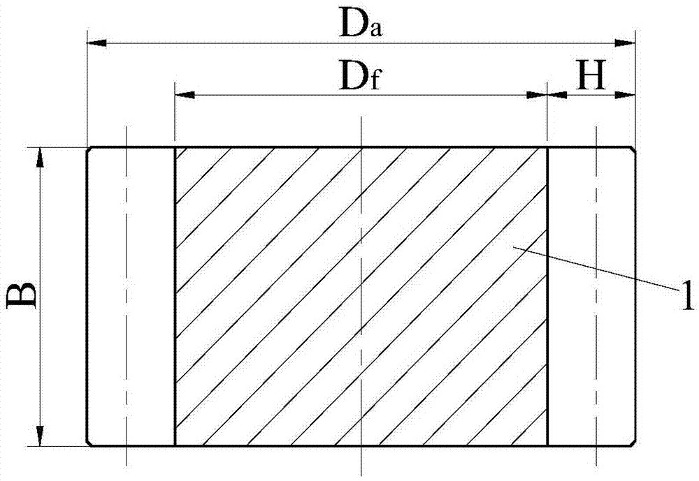
[0107] Take a cylindrical gear (tooth number z=12, modulus m=4, tooth width B=30mm, tooth height H=9mm. See attached figure 1 ) The precision forming process is an embodiment.

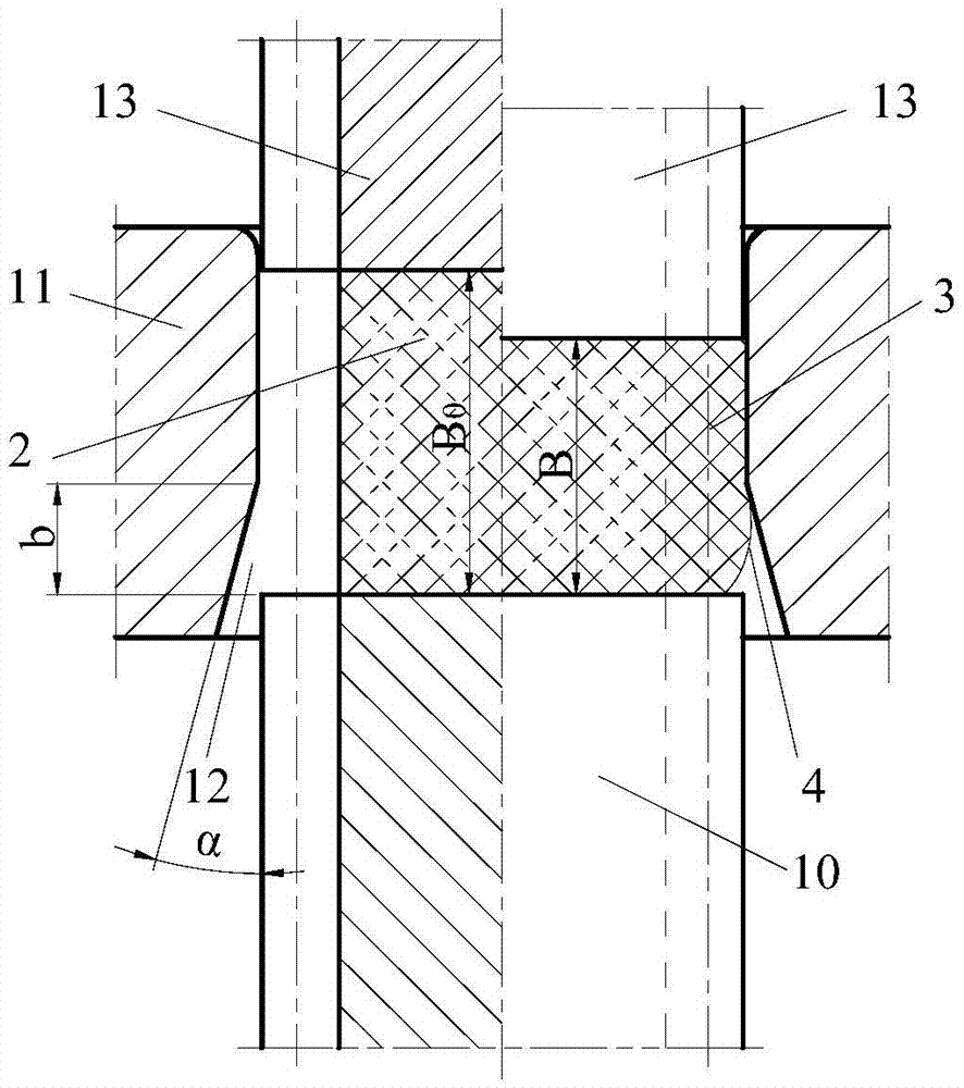
[0108] First introduce its precision forming mold. Mold is made up of lower punch 10, die 11, upper punch 13 (see attached image 3 , attached Figure 4 ).

[0109] The main body of the cavity of the die 11 is in a through shape, but the side walls are not completely straight-through, and the middle and lower sections of the tooth top cavity are cavity expansion spaces 12 (corresponding to the lower corner of the gear and the adjacent area, see the attached Figure 12 , attached Figure 13 , attached Figure 14 , attached Figure 15 , attached Figure 17 , attached Figure 18 ), the meridional plane size o...


PUM

PropertyMeasurementUnit
diameteraaaaaaaaaa
widthaaaaaaaaaa
heightaaaaaaaaaa

Abstract

The invention discloses a precision forming method for a straight/helical tooth cylinder gear with corners easy to fill and a die. During a closed die forging upsetting stage, a cylindrical blank is manufactured into an intermediate process part with lower corners not tidy enough in an upsetting mode; a volume protruding relative to a tooth outline is reserved near each lower corner of the intermediate process part; during an ejection-out stage, a lower convex die moves upwards, due to the function of a lateral wall conical surface of a concave die, the lower corners, not tidy enough, of the intermediate process part are deformed again, the protruding volumes transfer towards the lower corners, and forming of the lower corners is completed. According to the structure of the concave die, the conical surface with the bottom surface outline larger than the gear tooth top outline is used for expanding a concave die cavity near each lower corner, a cylindrical die cavity of the corresponding portion becomes a big-end-down prism-frustum-shaped die cavity, and the tooth root and the parts far away from the lower corners still keep the cylinder die cavity. By means of the precision forming method for the straight/helical tooth cylinder gear with the corners easy to fill and the die, the problems that according to traditional cylindrical gear precision forming, the gear tooth corners are not full enough, forming force is large, the structure of the die is complex, the service conditions are bad, the service life of the die is short, and the requirements for motions of equipment are complex are solved.

Description

technical field [0001] The invention belongs to the technical field of metal plastic forming technology, is mainly used in the manufacture of mechanical parts, relates to a gear tooth precision forming method and a mold thereof, and is especially suitable for straight teeth or helical cylindrical (cylindrical or non-cylindrical) , the following mainly take cylindrical gear as an example) gear precision forming. technical background [0002] Cylindrical gears (hereinafter referred to as gears) are mainly used to transmit force and motion in the same plane, and are widely used in various mechanical devices. A typical gear generally consists of a hub, spokes and a toothed rim. According to the shape of the tooth line, there are spur gears, helical gears, and herringbone gears. [0003] The traditional manufacturing process of gears is to first obtain the wheel blank with the tooth groove filled with excess blocks and simplified shape through forging or casting, and then remov...

Claims


Application Information

Patent Timeline
Patent Type & Authority Applications(China)
IPC IPC(8): B21K1/30B21J13/02
CPCB21J13/02B21K1/305
Inventor 张如华龙启博陈家叶亚彬徐强郭开元
Owner NANCHANG UNIV
Why Eureka
Try Eureka