Pull rod type inclined cutting machine convenient to transport

A technology of oblique cutting machine and pull rod type, which is applied in the direction of electromechanical devices, metal sawing equipment, metal processing machinery parts, etc., can solve the problems of high processing accuracy requirements for cages, low production and installation efficiency, and complicated cage installation, etc., to achieve The effects of reduced long-distance transportation, convenient transportation, and enhanced portability

Active Publication Date: 2016-03-30
CHANGZHOU CREATE ELECTRIC APPLIANCE
View PDF2 Cites 5 Cited by
  • Summary
  • Abstract
  • Description
  • Claims
  • Application Information

AI Technical Summary

Problems solved by technology

", it can be seen that the installation of the cage is more complicated, and the efficiency of production and installation is low
First of all, setting multiple cages in the same first groove is cumbersome to install and requires high machining accuracy of the cages. It is not only necessary to ensure that the connection between the cages is accurate but also to ensure that the cages can be just inserted into the first cage after they are connected. In the groove; secondly, it is necessary to ensure that the cages that are not in the same first groove correspond to each other in the axial direction of the casing, otherwise the permanent magnet will not be installed, and the installation efficiency will be greatly reduced; finally, each cage is embedded in the In the case, the first groove is opened on the inner rotating surface of the case, which is troublesome to process. At the same time, the thickness of the case needs to be increased accordingly, resulting in a corresponding increase in production costs.

Method used


Image

  • Pull rod type inclined cutting machine convenient to transport
  • Pull rod type inclined cutting machine convenient to transport
  • Pull rod type inclined cutting machine convenient to transport

Examples


Embodiment 1)

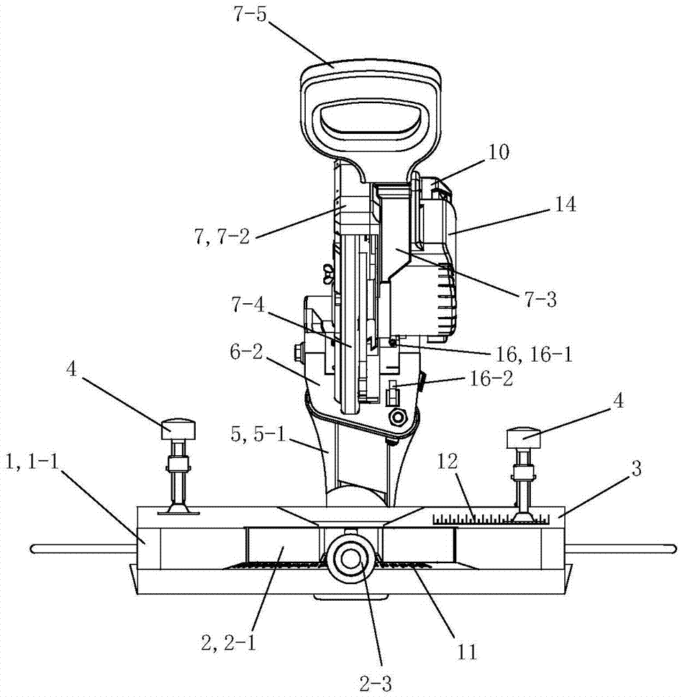
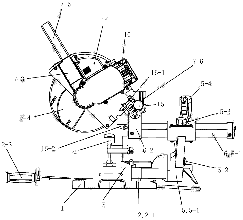
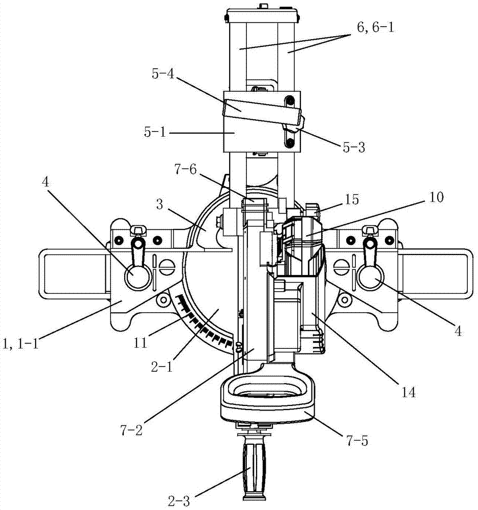
[0057] See Figure 1 to Figure 10 , the present invention is convenient to transport rod-type miter cutting machine including base 1, workbench 2, support 3, pressing device 4, rocker arm 5, slide bar assembly 6, fuselage 7, driving device 8, control device 9, Battery 10, saw blade 13, dust cover 14, body positioning device 15 and depth adjustment device 16.

[0058] See Figure 1 to Figure 10 , the base 1 is one piece. On the left and right sides of the base 1 are provided upwardly protruding supporting parts 1-1. An angle ruler 11 is provided on the front side of the middle part of the base 1 .

[0059] See Figure 1 to Figure 10 , The workbench 2 includes a turntable 2-1, a guard plate 2-2 and a workbench adjustment assembly 2-3. The turntable 2-1 of the workbench 2 is rotatably arranged on the base 1, between the support parts 1-1 on the left and right sides of the base 1, and the upper surface of the turntable 2-1 is at the same level as the upper surface of the supp...


PUM

PropertyMeasurementUnit
depthaaaaaaaaaa
thicknessaaaaaaaaaa

Abstract

The invention discloses a pull rod type inclined cutting machine convenient to transport. The pull rod type inclined cutting machine is characterized by comprising a base, a worktable, a support, a rocker arm assembly, a sliding rod assembly, a machine body, a drive device, a control device and a saw web. A rotation table of the worktable is arranged on the base in a rotating mode and is provided with a notch groove from front to back. The support is fixedly arranged in the back of the upper side of a supporting part of the base. The rocker arm assembly comprises a rocker arm, and the rocker arm is arranged at the rear end of the rotation table in a rotating mode and can turn to the left side or the right side. The machine body is arranged on the rocker arm through the sliding rod assembly. The drive device is a brushless direct current motor, a stator is fixedly arranged on the machine body, the axis of the stator is horizontally arranged from left to right, a brushless motor outer rotor assembly is arranged on the machine body through a corresponding bearing assembly in a rotating mode after a drive shaft of the brushless motor outer rotor assembly penetrates through the stator from right to left, and the corresponding part of the stator is located in a motor case. The saw web is detachably fixed to the drive shaft of the brushless motor outer rotor assembly of the drive device. The drive device is electrically connected to the control device.

Description

[0001] This invention is a divisional application of the invention patent application with the application number 201410385347.2, the application date is August 06, 2014, and the invention name is "tie rod type oblique cutting machine". technical field [0002] The invention relates to the field of cutting machines, in particular to a rod-type oblique cutting machine with a saw blade that can move along its radial direction. Background technique [0003] As a cutting tool that can cut both metal materials and non-metal materials, the bevel cutting machine is widely used in various industries. The oblique cutting machine is easy to operate and has high cutting efficiency. During the cutting operation, hold the operating handle and press down to perform the cutting operation; when the workpiece to be cut is wide, the operating handle can be pulled to make the saw blade move radially, thereby cutting the workpiece; when cutting at a certain angle, you can use the Adjust the ro...

Claims


Application Information

Patent Timeline
Patent Type & Authority Applications(China)
IPC IPC(8): B23D45/14B23Q5/10B23Q3/00B23Q17/22B23Q11/08B23Q11/00
CPCB23D45/14B23D47/02B23Q3/00B23Q5/10B23Q11/0003B23Q11/08B23Q17/2233H02K1/30H02K5/04H02K5/20
Inventor 葛树兴李玉红张小荣
Owner CHANGZHOU CREATE ELECTRIC APPLIANCE
Why Eureka
Try Eureka