
Laser cutting device and laser head thereof

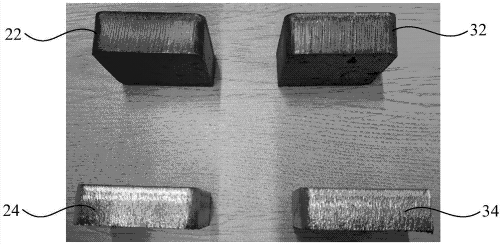
A technology of laser head and rectifier tube, which is applied in the direction of laser welding equipment, welding equipment, metal processing equipment, etc., can solve the problems of weakening laser optical quality, reducing the quality of cutting section, and affecting processing quality, so as to improve the uniformity of airflow distribution, The effect of reducing the roughness of the processed surface and improving the cutting quality

Active Publication Date: 2016-03-30
HANS LASER TECH IND GRP CO LTD
View PDF5 Cites 13 Cited by
  • Summary
  • Abstract
  • Description
  • Claims
  • Application Information

AI Technical Summary

Problems solved by technology

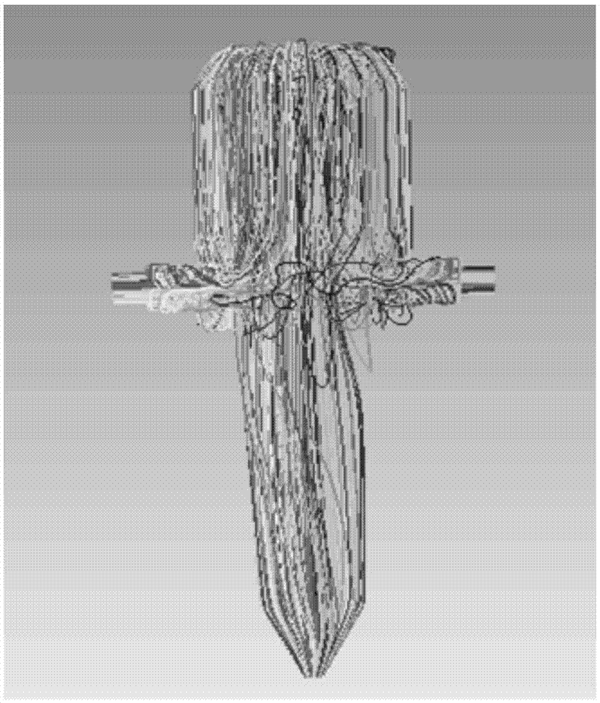
The degradation of laser coherence will seriously weaken the optical quality of the laser, causing random drift of light and redistribution of laser energy on the beam section, including distortion, broadening, and fragmentation.
In laser thick plate processing, the processing quality of the workpiece is seriously affected by the quality of the laser beam, and the unsatisfactory beam quality will cause impenetrable cutting, low cutting efficiency, or a decrease in the quality of the cut section.

Method used


Image

  • Laser cutting device and laser head thereof
  • Laser cutting device and laser head thereof
  • Laser cutting device and laser head thereof

Examples


Embodiment Construction

[0032] In order to facilitate the understanding of the present invention, a more comprehensive description of the laser cutting device and its laser head will be given below with reference to the relevant drawings. A preferred embodiment of a laser cutting device and its laser head is shown in the accompanying drawings. However, the laser cutting device and its laser head can be implemented in many different forms and are not limited to the embodiments described herein. On the contrary, the purpose of providing these embodiments is to make the disclosure of the laser cutting equipment and its laser head more thorough and comprehensive.

[0033] Unless otherwise defined, all technical and scientific terms used herein have the same meaning as commonly understood by one of ordinary skill in the technical field of the invention. The terms used herein in the description of the laser cutting equipment and its laser head are only for the purpose of describing specific embodiments, a...


PUM


Abstract

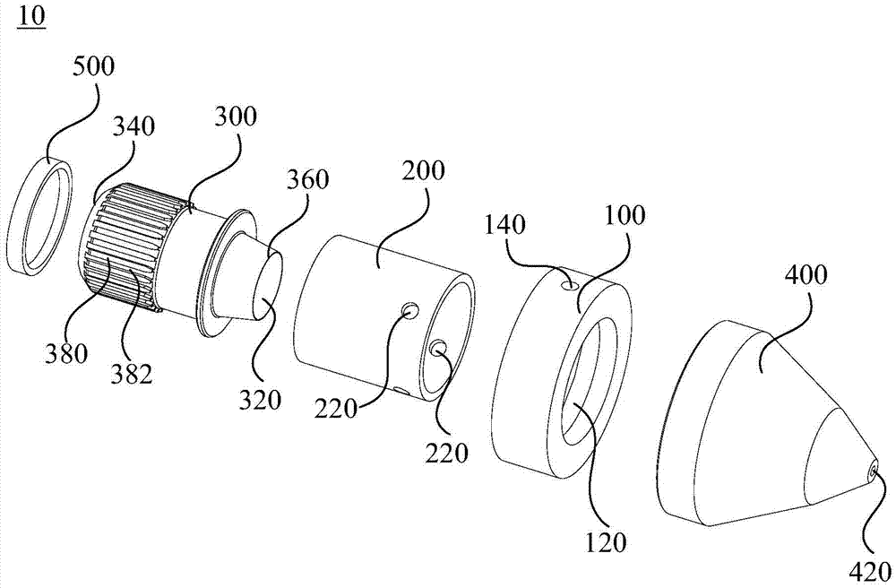
The invention relates to a laser cutting device and a laser head thereof. The laser head comprises an air inlet ring, a first rectifier tube, a second rectifier tube and an air nozzle. An annular groove is formed in the inner side of the air inlet ring, and air inlet holes communicated to the groove are formed in the outer side of the air inlet ring; ventilation holes are formed in the side wall of the first rectifier tube, the first rectifier tube is sleeved with the air inlet ring, and the ventilation holes are communicated with the groove; an air flow passage is formed inside the second rectifier tube, and the second rectifier tube comprises a first end and a second end which are opposite; the second rectifier tube is sleeved with the first rectifier tube, and a rectifying passage is formed between the first rectifier tube and the second rectifier tube; and an air outlet gap is formed between the first rectifier tube and the first end, and the air flow passage and the rectifying passage are communicated through the air outlet gap. Due to two times of rectifying, the airflow distribution evenness of cutting air can be improved, and the intensity of turbulence can be reduced, so that the influence of the pneumatic optical effect on a laser path is reduced, the stability of the quality of laser beams is guaranteed, the roughness of the machined surface is reduced, and the perpendicularity of cut lines is improved.

Description

technical field [0001] The invention relates to the technical field of laser processing, in particular to a laser cutting device and a laser head thereof. Background technique [0002] In the laser cutting thick plate process, the most important criteria to measure the cutting quality are the surface roughness and verticality of the thick plate cutting section. Cutting airflow is one of the most important factors affecting the quality of cut sections of thick plates. Among them, the cutting gas path design will seriously affect the gas turbulence distribution, optical path transmission and lens protection performance. When the laser propagates in the turbulent flow, the fluctuation of the refractive index of the gas caused by the turbulent flow will cause the distortion of the laser wavefront and destroy the coherence of the laser. The degradation of laser coherence will seriously weaken the optical quality of the laser, causing random drift of light and redistribution of ...

Claims


Application Information

Patent Timeline
Patent Type & Authority Applications(China)
IPC IPC(8): B23K26/70B23K26/14B23K26/38
CPCB23K26/1435B23K26/38
Inventor 范国成万虹龚欢肖俊君陈根余陈燚高云峰
Owner HANS LASER TECH IND GRP CO LTD
Learn More