
Hyperspectral rotating mirror scanning imaging system and imaging method based on rotor UAV

A scanning imaging and unmanned rotor technology, applied in the field of hyperspectral imaging of rotor UAVs, can solve problems such as image distortion and poor image acquisition quality, and achieve the effects of improving quality, simple control, and convenient adjustment

Active Publication Date: 2017-08-08
SICHUAN DUALIX SPECTRAL IMAGING TECHNOLOGY CO LTD
View PDF6 Cites 0 Cited by
  • Summary
  • Abstract
  • Description
  • Claims
  • Application Information

AI Technical Summary

Problems solved by technology

[0013] The present invention aims to solve the problem in the prior art that a speed relationship similar to a cosine function relationship occurs due to poor image acquisition quality caused by the unsteady flight of the drone and inconsistent speeds at the beginning and end of the scan and the middle section, resulting in image distortion. A hyperspectral rotating mirror scanning imaging system and imaging method based on a rotor UAV is provided. The UAV is used as the stage of the hyperspectral rotating mirror scanning imaging system, and the aircraft is remotely controlled through wireless transmission. When the man-machine flies and stops to the designated area, the hyperspectral rotating mirror scanning imaging system uses rotating mirror scanning to collect images, thereby improving the quality of the collected images; The images can be kept at a constant speed, which eliminates the cosine phase difference generated when the rotating mirror is scanned, and avoids image distortion

Method used


Image

  • Hyperspectral rotating mirror scanning imaging system and imaging method based on rotor UAV
  • Hyperspectral rotating mirror scanning imaging system and imaging method based on rotor UAV
  • Hyperspectral rotating mirror scanning imaging system and imaging method based on rotor UAV

Examples


Embodiment Construction

[0038] The present invention will be further described below in conjunction with the embodiments, and the described embodiments are only a part of the embodiments of the present invention, not all of them. Based on the embodiments of the present invention, other used embodiments obtained by persons of ordinary skill in the art without creative efforts all belong to the protection scope of the present invention.

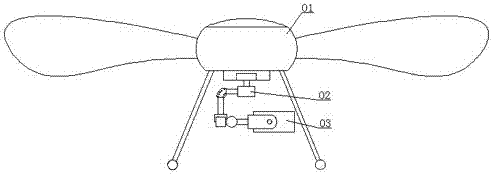
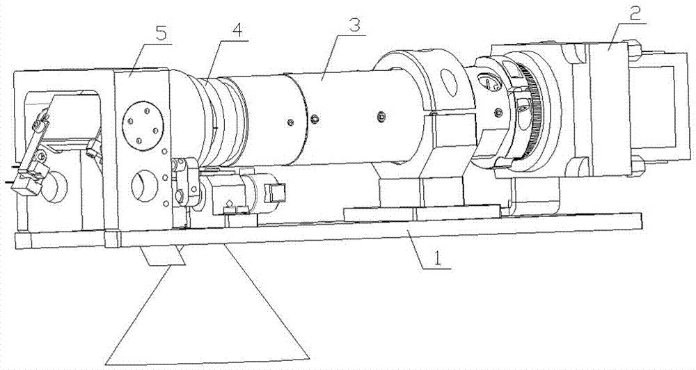
[0039] combine Figure 1 to Figure 7 , the hyperspectral rotating mirror scanning imaging system based on the rotor UAV of the present invention includes a UAV 01 and a control module for controlling the flight of the UAV, and the UAV 01 is connected with a hyperspectral rotating mirror scanning imaging system 03, Wherein, the UAV and the control module for controlling the flight of the UAV belong to the prior art products, which are understood and understood by those skilled in the art, and will not be repeated here.

[0040] As a preferred mode of the present inven...


PUM


Abstract

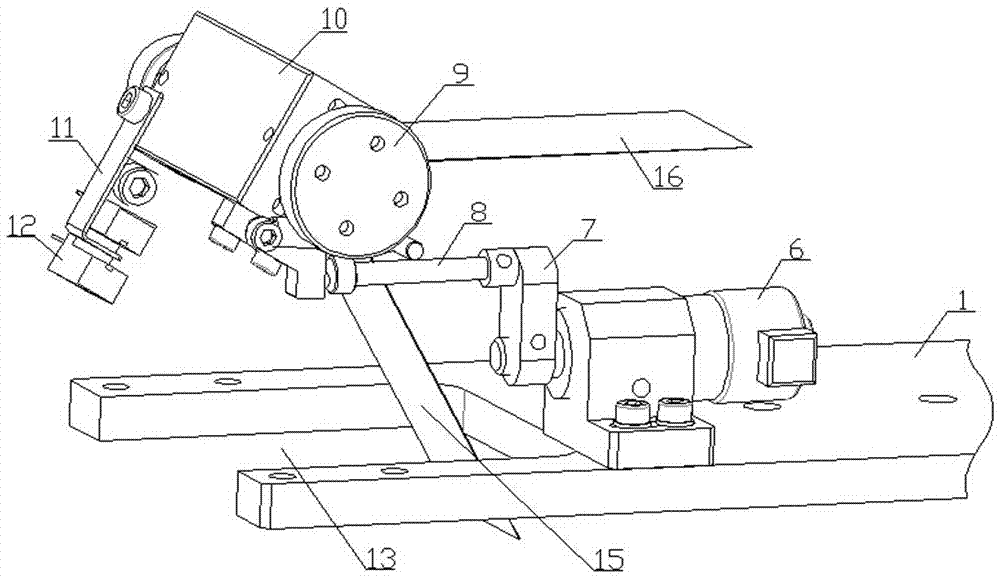
The invention belongs to the technical field of hyper-spectral imaging of an unmanned gyroplane and discloses a hyper-spectral rotating mirror scanning imaging system based on the unmanned gyroplane and an imaging method thereof, is used for solving the problem of poor image acquisition quality caused by bumpy flight of an unmanned aerial vehicle in the prior art. In the invention, the unmanned aerial vehicle and a control module are adopted; the unmanned aerial vehicle is connected with the hyper-spectral rotating mirror scanning imaging system; the hyper-spectral rotating mirror scanning imaging system comprises a bottom plate; an imaging lens, an imaging spectrometer and a camera are installed on the bottom plate; the imaging spectrometer is connected between the imaging lens and the camera; a scanning rotating mirror device is installed at the front end of the imaging lens; the scanning rotating mirror device comprises a rotating shaft which is fixedly installed; the rotating shaft is sleeved with a rotating mirror lens base capable of rotating on the rotating shaft; a rotating mirror lens is installed on the rotating mirror lens base; the rotating mirror lens base is connected with a push rod; and the push rod is connected with a linear motor.

Description

technical field [0001] The invention belongs to the technical field of hyperspectral imaging of a rotor UAV, and in particular relates to a hyperspectral rotating mirror scanning imaging system and an imaging method based on a rotor UAV. Background technique [0002] The development of remote sensing technology has gone through panchromatic (black and white), color photography, and multi-spectral scanning imaging stages. The imaging spectrum technology that appeared in the early 1980s brought optical remote sensing into a new stage—the stage of hyperspectral remote sensing. The so-called hyperspectral remote sensing refers to the remote sensing science and technology with high spectral resolution. The imaging spectrometer used in the imaging spectroscopy technology can acquire many very narrow and continuous spectrum in the ultraviolet, visible, near-infrared and short-wave infrared regions of the electromagnetic spectrum. image data. Imaging spectrometers provide each pixe...

Claims


Application Information

Patent Timeline
Patent Type & Authority Patents(China)
IPC IPC(8): B64D47/08G01J3/28
CPCB64D47/08G01J3/2823
Inventor 陈兴海张卓刘业林曹佳宝
Owner SICHUAN DUALIX SPECTRAL IMAGING TECHNOLOGY CO LTD
Learn More