Method for three-dimensional reconstruction of defected part of tip of aeroengine compressor blade

An aero-engine and three-dimensional reconstruction technology, which is applied in the field of machine vision, can solve the problems of a long time consumption, a rapid reconstruction method of a three-dimensional model of a missing part of a blade tip of an aero-engine compressor blade, and a limited scope of application.

Active Publication Date: 2016-03-30
HEBEI UNIV OF TECH
View PDF4 Cites 11 Cited by
  • Summary
  • Abstract
  • Description
  • Claims
  • Application Information

AI Technical Summary

Problems solved by technology

However, the problem with this method is that it is only applicable to turbine blades with blade tip defects ranging from 0.5 to 2 mm, the scope of application is limited, and it takes a long time
[0005] Within the scope of the applicant's search, there is no relevant literature report on the rapid reconstruction of the 3D model of the tip defect of the aeroengine compressor blade using the boundary extension method

Method used


Image

  • Method for three-dimensional reconstruction of defected part of tip of aeroengine compressor blade
  • Method for three-dimensional reconstruction of defected part of tip of aeroengine compressor blade
  • Method for three-dimensional reconstruction of defected part of tip of aeroengine compressor blade

Examples


Embodiment Construction

[0026] The present invention will be further described in detail below in conjunction with the embodiments and accompanying drawings. The examples are only used to further describe the present invention in detail, and do not limit the protection scope of the claims of the present application.

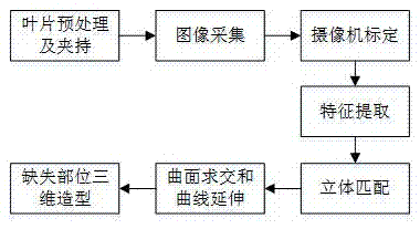
[0027] Aeroengine compressor blade tip (abbreviation blade) defect position three-dimensional model (abbreviation three-dimensional) reconstruction method (abbreviation or method, see for short) of the present invention design Figure 1-8 ) is as follows, after detection, the maximum distance between the blade defect vertex and the defect plane is 4.35mm, and the steps of the reconstruction method are as follows:

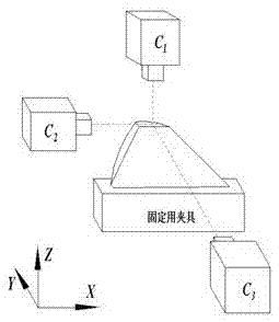
[0028] 1) Blade pretreatment and clamping; pick out repairable blade tip defects, and remove the oxide layer on the blade tip surface by machining; then stably clamp the machined blades with fixed fixtures, and require parallel to the horizontal plane;

[0029] 2) image acq...


PUM


Abstract

The invention discloses a method for the three-dimensional reconstruction of a defected part of the tip of an aeroengine compressor blade, and the method comprises the steps: 1), carrying out the preprocessing and clamping of the blade, removing an oxidation layer of a defected blade, clamping the blade, and enabling the to-be-welded cross section of the blade to be parallel to a horizontal plane; 2), carrying out image collection, building a three-eye stereoscopic vision measurement system, obtaining a three-dimensional gray scale image of the blade, and obtaining an edge image through edge detection; 3), calibrating a camera, completing the three-dimensional calibration of a vision system, and obtaining the conversion relation between camera image coordinates and the world coordinate system; (4), carrying out feature extraction, and obtaining the information of feature points from the edge image in a mode of combining edge tracking and feature point extraction; 5), stereo matching: carrying out the matching of the calibrated vision system, constructing a three-dimensional coordinate system of the blade, and obtaining a three-dimensional edge structure of the blade; 6), carrying out curved surface intersection and extension; 7), carrying out the three-dimensional molding of the defected part, carrying out fitting and reconstruction, and obtaining the structural data of the defected part of the blade.

Description

technical field [0001] The invention belongs to the technical field of machine vision, and in particular relates to a three-dimensional reconstruction method for a blade tip defect part of an aeroengine compressor blade. Background technique [0002] The blade is the heart of the aeroengine compressor, but due to its harsh working environment, it will be worn or broken after a certain period of time. In order to save replacement costs, repairing damaged compressor blades that meet airworthiness requirements has significant economic benefits and practical value. There are strict restrictions on whether the blade tip can be repaired (see Dong Kaifu. Research on multi-frequency phase expansion in the grating projection measurement system for aeroengine blades [D]. Tianjin: Hebei University of Technology, 2013). According to statistics, blades that need to be repaired by welding account for more than half of the total blade repair business. At present, the compressor blades of...

Claims


Application Information

Patent Timeline
Patent Type & Authority Applications(China)
IPC IPC(8): G06T17/00G06T7/00
CPCG06T17/00G06T2200/08
Inventor 戴士杰李伟超霍梦华
Owner HEBEI UNIV OF TECH
Why Eureka
Try Eureka