
Overcurrent protection circuit and liquid crystal display

An overcurrent protection circuit and circuit technology, used in static indicators, instruments, etc., can solve the problems of liquid crystal display stop working, false triggering of OCP operation, large spike current, etc.

Active Publication Date: 2016-03-30
TCL CHINA STAR OPTOELECTRONICS TECH CO LTD
View PDF9 Cites 75 Cited by
  • Summary
  • Abstract
  • Description
  • Claims
  • Application Information

AI Technical Summary

Problems solved by technology

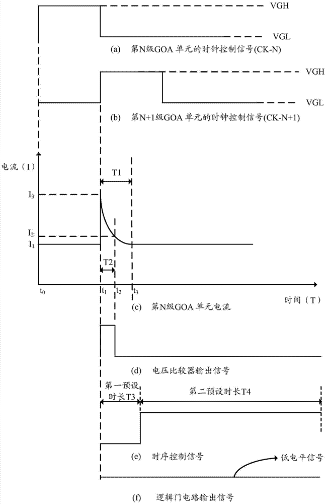
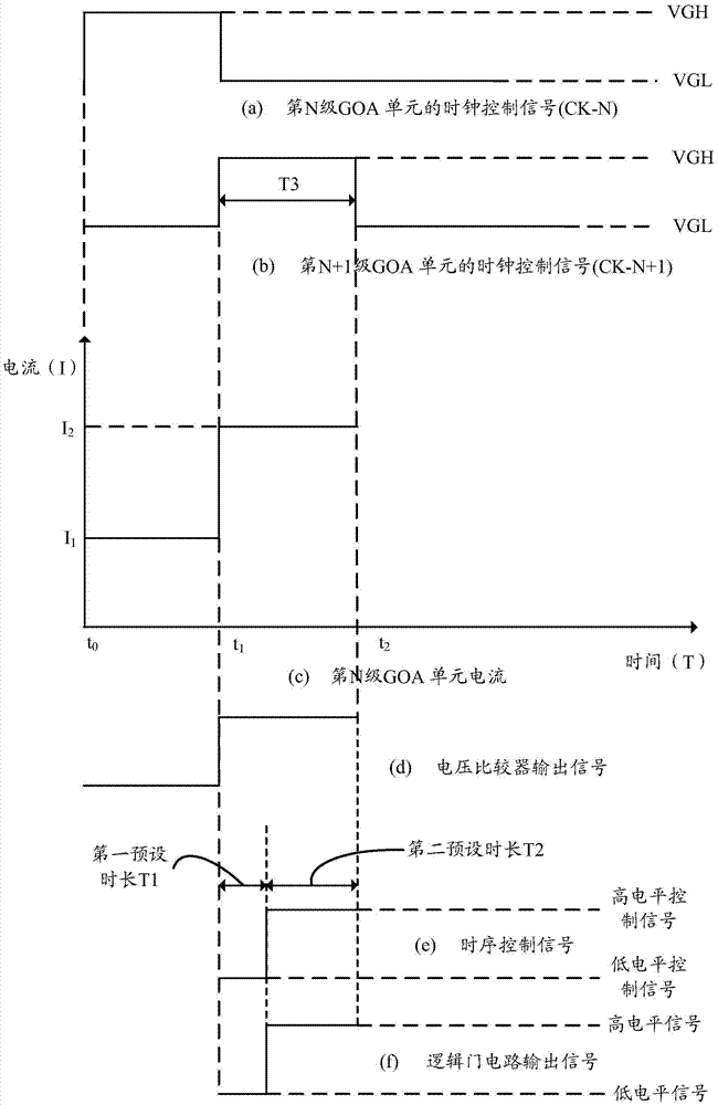
However, when the TFTs in the current row (such as the Nth row) are turned on, the TFTs in the current row may be disturbed by the activation of the TFTs in the next row (such as the N+1th row), and the GOA circuit corresponding to the TFT in the current row will generate An instantaneous large spike current, which falsely triggers the OCP operation, causing the LCD to stop working

Method used


Image

  • Overcurrent protection circuit and liquid crystal display
  • Overcurrent protection circuit and liquid crystal display
  • Overcurrent protection circuit and liquid crystal display

Examples


Embodiment Construction

[0025] The following will clearly and completely describe the technical solutions in the embodiments of the present invention with reference to the drawings in the embodiments of the present invention. Apparently, the described embodiments are some, not all, embodiments of the present invention. Based on the implementation manners in the present invention, all other implementation manners obtained by persons of ordinary skill in the art without making creative efforts shall fall within the protection scope of the present invention.

[0026] In addition, the following descriptions of the various embodiments refer to the attached drawings to illustrate specific embodiments in which the present invention can be implemented. The directional terms mentioned in the present invention, for example, "upper", "lower", "front", "rear", "left", "right", "inner", "outer", "side", etc., only is to refer to the direction of the attached drawings. Therefore, the direction terms used are for ...


PUM


Abstract

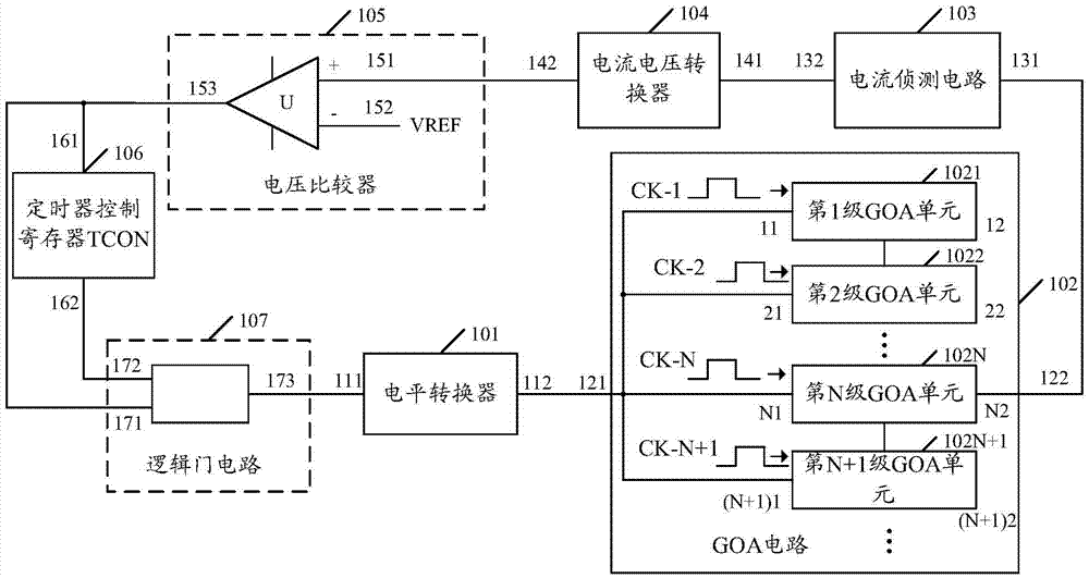
The embodiment of the invention discloses an overcurrent protection circuit, and the circuit comprises a level converter and a substrate array line drive (GOA) circuit in electrical connection with the level converter. The circuit also comprises a current detection circuit, a current-voltage converter, a voltage comparator, a timer control register, and a logic gate circuit. The GOA circuit is connected with the current detection circuit, and the current detection circuit is connected with the current-voltage converter. The current-voltage converter is connected with the in-phase input end of the voltage comparator, and the inverted-phase input end of the voltage comparator is connected with a reference voltage. The output end of the voltage comparator is connected with the input end of the timer control register and the first input end of the logic gate circuit. The output end of the timer control register is connected with the second input end of the logic gate circuit. The output end of the logic gate circuit is connected with the level converter. According to the embodiment of the invention, the circuit can prevent the wrong triggering of an overcurrent protection operation. The invention also provides a liquid crystal display comprising the circuit.

Description

technical field [0001] The invention relates to the technical field of liquid crystal display, in particular to an overcurrent protection circuit and a liquid crystal display. Background technique [0002] Gate Driver On Array (GOA) technology is a technology that manufactures a thin film transistor (Thin Film Transistor, TFT) gate scanning drive circuit on an array substrate to replace a driver chip made of an external silicon chip. Since the GOA circuit can be directly fabricated around the panel, the frame thickness of the panel of the Liquid Crystal Display (LCD) can be reduced, the manufacturing process can be simplified, the product cost can be reduced, and the integration degree of the LCD panel can be improved. [0003] The gate voltage of each row of TFTs in the liquid crystal display can be provided by a GOA circuit. In the GOA circuit, a level shifter (LevelShifter) is generally used to generate a clock control signal to control each row of TFTs to be turned on or...

Claims


Application Information

Patent Timeline
Patent Type & Authority Applications(China)
IPC IPC(8): G09G3/36
CPCG09G3/3677G09G2330/04
Inventor 李文芳
Owner TCL CHINA STAR OPTOELECTRONICS TECH CO LTD
Learn More