Thermal mass flow meter

一种质量流量计、质量流量的技术,应用在测量流量/质量流量、使用热变量测量流体速度、测量装置等方向,能够解决温度平衡破坏、热式流量计破损、传感器部热劣化等问题

Active Publication Date: 2016-03-30
HITACHI ASTEMO LTD
View PDF7 Cites 7 Cited by
  • Summary
  • Abstract
  • Description
  • Claims
  • Application Information

AI Technical Summary

Problems solved by technology

If water droplets adhere to the sensor part, the temperature balance will be broken and a part of the sensor part will be overheated locally, and the sensor part may be thermally degraded or the thermal flowmeter itself may be damaged.

Method used


Image

  • Thermal mass flow meter
  • Thermal mass flow meter
  • Thermal mass flow meter

Examples


no. 1 approach

[0056] pass Figure 1 ~ Figure 4 A thermal mass flowmeter according to a first embodiment of the present invention will be described.

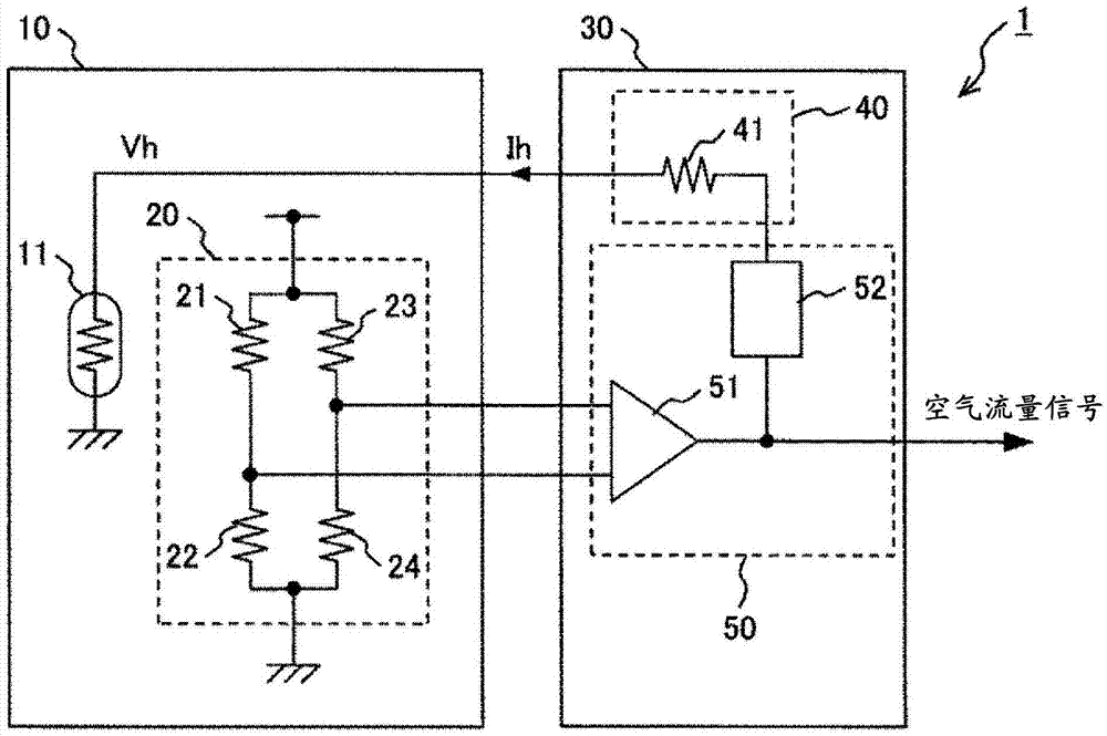
[0057] figure 1 It is a schematic circuit diagram showing the configuration of the thermal mass flowmeter of the first embodiment. Such as figure 1 As shown, the thermal mass flowmeter 1 of the first embodiment has: a sensor element unit 10 having a heating element 11 that generates heat by energization and a temperature detection bridge circuit 20 that detects the temperature of the heating element 11; The circuit unit 30 is connected to the sensor element unit 10 and controls the conduction of electricity to the heating element 11 . The temperature detection bridge circuit 20 is composed of a temperature detection resistor 21 whose resistance value changes according to temperature, and constant resistors 22 to 24 whose resistance value is constant.

[0058] The sensor element drive circuit unit 30 has an output mechanism 50 and an output...

no. 2 approach

[0070] pass Figure 5-11 A thermal mass flowmeter according to a second embodiment of the present invention will be described.

[0071] Figure 5 It is a schematic circuit diagram showing the configuration of the thermal mass flowmeter of the second embodiment. Such as Figure 5As shown, the thermal mass flowmeter 2 of the second embodiment has the same configuration as the sensor element unit 10 of the thermal mass flowmeter 1 of the first embodiment, but the sensor element drive circuit unit 31 has a different configuration. The sensor element drive circuit unit 31 of the present embodiment has an output mechanism 70 and an output impedance adjustment mechanism 60 .

[0072] The output mechanism 70 has: an amplifier 71, which detects the output voltage of the temperature detection bridge circuit 20; a MOS transistor 72, which receives the output of the amplifier 71; a resistor 73 and a MOS transistor 74 connected in series with the MOS transistor 72; a MOS transistor 75, ...

no. 3 approach

[0080] pass Figure 12 A thermal mass flowmeter according to a third embodiment of the present invention will be described.

[0081] Figure 12 It is a schematic circuit diagram showing the configuration of the thermal mass flowmeter of the third embodiment. Such as Figure 12 As shown, the thermal mass flowmeter 3 of the third embodiment has a sensor element unit 10 and a sensor element drive circuit unit 32 , and the sensor element drive circuit unit 32 has an output mechanism 70 and an output impedance adjustment mechanism 65 . That is, the thermal mass flowmeter 3 of the third embodiment differs from the thermal mass flowmeter 2 of the second embodiment in the output impedance adjustment mechanism 65 .

[0082] The output impedance adjustment mechanism 65 is different from the output impedance adjustment mechanism 60 in that the resistor 63 is arranged in the rear stage of the MOS transistor 62, and the output impedance of the sensor element drive circuit section 32 is ...


PUM


Abstract

To provide a thermal mass flow meter that makes enhanced gas flow rate measurement accuracy possible while securing thermal mass flow meter reliability (while preventing degradation and damage resulting from droplet adhesion), a thermal mass flow meter according to the present invention is characterized by having a heat-generating element that generates heat by having electric current passed therethrough, a temperature detection bridge circuit that detects the temperature of the heat generating element, and a sensor element drive circuit unit that is connected to the heat generating element and the temperature detection bridge circuit and controls the passing of electric current through the heat generating element; in that the sensor element drive circuit unit has an output mechanism and an output impedance adjustment mechanism; and in that the output impedance adjustment mechanism is provided between the output mechanism and the heating-generating element and has an output impedance that is higher than the electrical resistance value of the heat-generating element and is less than 1 M[Ohm].

Description

technical field [0001] The present invention relates to a flow measuring device for compressive fluid, in particular to a thermal mass flowmeter for measuring the mass flow of an air flow based on the heat transfer from a heating element of the air flow. Background technique [0002] As a device for measuring the flow rate of compressive fluid such as gas, there is a thermal mass flow meter (also simply referred to as a thermal flow meter), which is widely used as a device for measuring the amount of intake air in an electronically controlled fuel injection device of an internal combustion engine, for example. . If foreign matter adheres to the sensor part, the measurement accuracy will be extremely reduced, so it is generally required to use a thermal mass flowmeter in a clean airflow environment. [0003] However, in the actual use environment of electronically controlled fuel injection devices, etc., condensation may occur due to changes in temperature and humidity, and ...

Claims


Application Information

Patent Timeline
Patent Type & Authority Applications(China)
IPC IPC(8): G01F1/698G01P5/12
CPCG01P5/12G01F1/6845G01F1/696G01F1/698G01F1/699G01F1/69
Inventor 松本昌大中野洋浅野哲小野濑保夫
Owner HITACHI ASTEMO LTD
Why Eureka
Try Eureka