Method for machining narrow groove in planing mode by numerical control boring and milling machine

A boring-milling machine and narrow-slot technology, which is applied to the CNC boring-milling machine for planing and processing narrow slots, and the narrow slot machining field with circumferential radiation distribution on the gas turbine exhaust takeover heat insulation component, which can solve the problem of large diameter, high cost, and the thickness of the saw blade. Small and other problems, to ensure the quality of processing, easy operation, and improve processing efficiency.

Active Publication Date: 2016-04-06
YICHANG MARINE DIESEL ENGINE
View PDF5 Cites 3 Cited by
  • Summary
  • Abstract
  • Description
  • Claims
  • Application Information

AI Technical Summary

Problems solved by technology

Saw blades are small in thickness and large in diameter, requiring special manufacturing, and the cost is very high

Method used


Image

  • Method for machining narrow groove in planing mode by numerical control boring and milling machine
  • Method for machining narrow groove in planing mode by numerical control boring and milling machine
  • Method for machining narrow groove in planing mode by numerical control boring and milling machine

Examples


Embodiment Construction

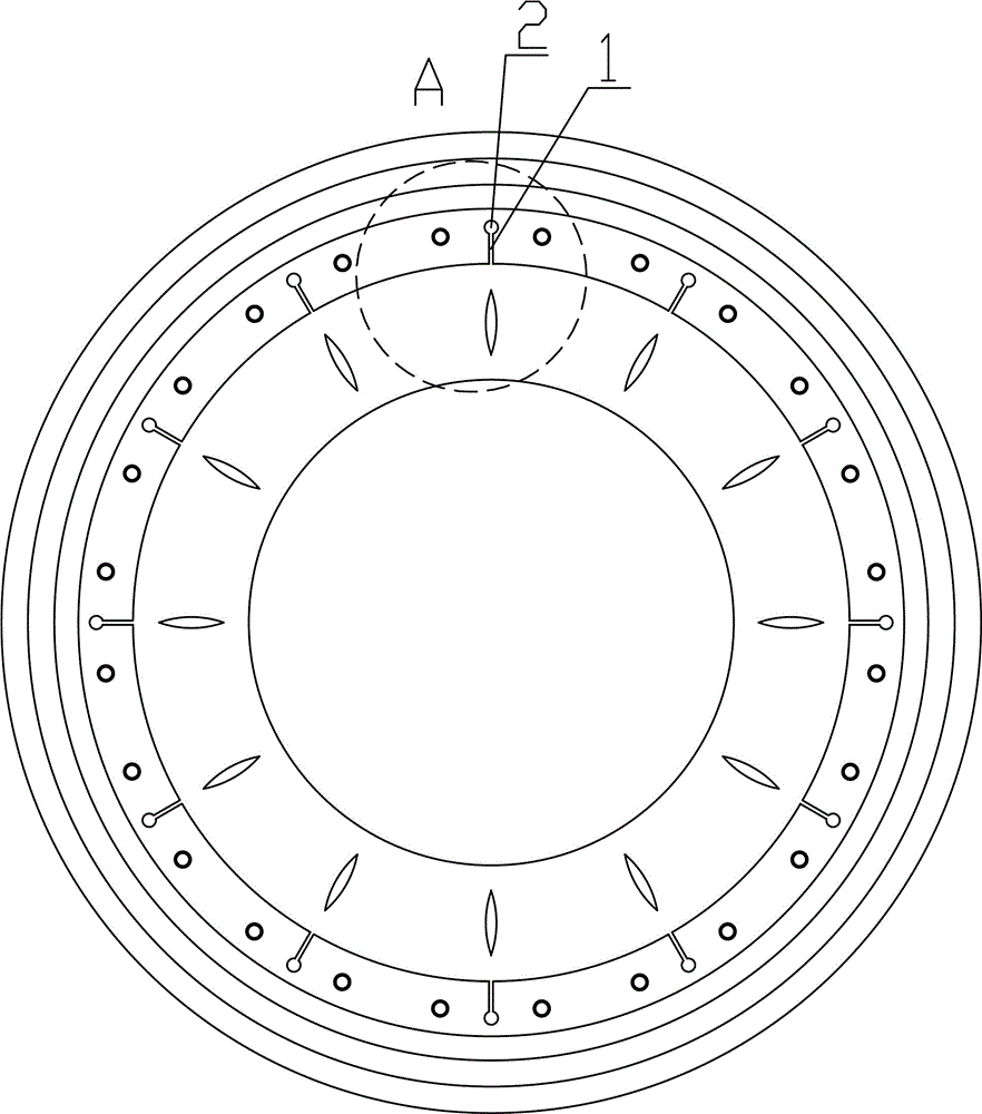
[0025] Such as Figure 1~5 Among them, a method for planing and processing narrow slots with a CNC boring and milling machine, comprising the following steps:

[0026] 1. Clamp the workpiece so that the processing surface is parallel to the main shaft 3 of the CNC boring and milling machine, and the length direction of the narrow groove 1 is parallel to the main shaft 3;

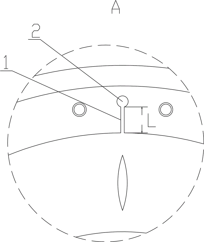
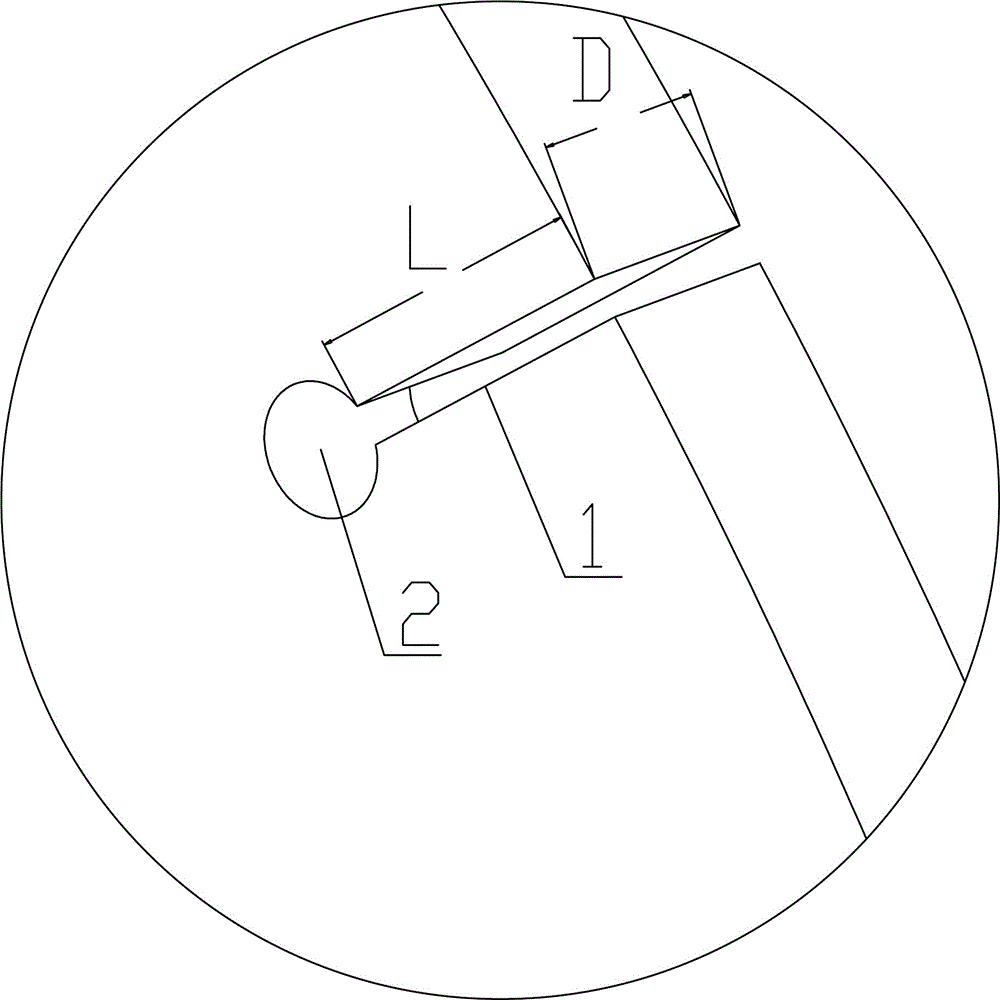
[0027] 2. Clamp and correct the tool so that the machining direction of the boring tool 6 is consistent with the length direction of the narrow slot 1, for example image 3 As shown by L in , the feeding direction is consistent with the thickness direction of the narrow groove 1, for example image 3 as shown in D;

[0028] In the preferred scheme, the boring head is installed on the CNC boring and milling machine, and the tool seat 5 of the boring head is connected with the main shaft 3, and the end face of the tool seat 5 is provided with a lower end and at least one side open knife groove 7, one of the ...


PUM


Abstract

The invention provides a method for machining a narrow groove in a planing mode by a numerical control boring and milling machine. The method comprises the steps of 1, clamping a work-piece and enabling the machining face to be parallel with a main shaft of the numerical control boring and milling machine and the length direction of the narrow groove to be parallel with the direction of the main shaft; 2, clamping and correcting a cutter and enabling the machining direction of the boring cutter to be parallel with the length direction of the narrow groove and the feed direction to be parallel with the thickness direction of the narrow groove; 3, fixing the main shaft; 4, carrying out programming machining, wherein a numerical control shaft parallel with the length direction of the narrow groove to be machined does the main cutting motion, a numerical control shaft parallel with the depth direction of the narrow groove to be machined does the feed motion and then a program is started for machining. Through the steps, the numerical control boring and milling machine can be used for machining the narrow groove in the planing mode. By adopting the numerical control boring and milling machine for machining the narrow groove, the machining efficiency is improved, the machining quality is guaranteed, the operation is simple, convenient and practicable, and the width of the groove is easy to control. By adopting the method, the efficiency of machining the narrow groove is 2-5 times that of machining the narrow groove by an end mill, and the economic benefit of machining the groove with the width ranging from 2 mm to 4 mm is the most remarkable.

Description

technical field [0001] The invention relates to the field of machining, in particular to a method for planing and machining narrow grooves by a numerically controlled boring and milling machine. It is especially suitable for machining the narrow grooves of the circumferential radiation distribution on the heat insulation parts of gas turbine exhaust pipes. The present invention can also be used for through-groove processing of some special parts due to narrow space and interference of accessories, which cannot be processed by ordinary boring and milling, such as keyway processing of some parts on a boring and milling machine. Background technique [0002] The exhaust connection pipe is the exhaust channel of the gas turbine. The inside of the exhaust connection pipe is attached with a heat insulation layer. The heat insulation layer component is designed with a number of narrow grooves of 2 to 4mm radially distributed along the circumference. See figure 1 . In traditional ...

Claims


Application Information

Patent Timeline
Patent Type & Authority Applications(China)
IPC IPC(8): B23D1/08B23D11/00
CPCB23D1/08B23D11/00
Inventor 王嵩
Owner YICHANG MARINE DIESEL ENGINE
Why Eureka
Try Eureka