

Tank sleeving technological method of railway tank car of double-layer structure
A technology of double-layer structure and process method, applied in auxiliary devices, manufacturing tools, metal processing, etc., can solve the problems that the structure is not suitable for the overall assembly of the double-layer tank structure of railway tank cars, the assembly method cannot be realized, and the heat insulation material is damaged. Achieve the effects of reducing quality risk, easy process control, and reducing the impact of production tact
- Summary
- Abstract
- Description
- Claims
- Application Information
AI Technical Summary
Problems solved by technology
Method used
Image

Examples
Embodiment
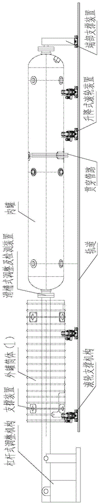
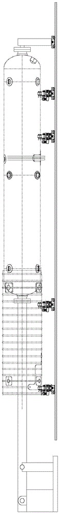
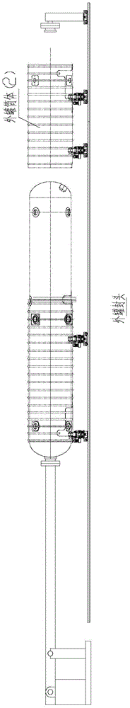
[0029] Below in conjunction with the accompanying drawings, the present invention will be further described by taking the new LNG railway tank car tank body fitting process method as an example, but it is not limited to the vehicle type and the tank body structure of this type.
[0030] Technical requirements: The minimum distance between the inner and outer tank interlayer space is about 20mm; the outer tank body cannot touch the heat insulation material laid on the outer surface of the inner tank during the assembly process, causing damage to the heat insulation material; the axial center offset of the inner and outer tank bodies is not It is larger than 5mm; the interlayer is non-contact after the inner and outer overall sets, and the whole is airtight.
[0031] a. Drop the outer tank body 1 onto the roller support device and adjust the positioning; fix one end of the inner tank on the chute-type adjustment and detection device through the flange form, and fix the other end ...
PUM
 Abstract
Description
Claims
Application Information