
Movable urea injection machine and moving method thereof

A filling machine, mobile technology, applied in special distribution devices, packaging, distribution devices, etc., can solve problems such as unfavorable promotion and application, heavy installation, use cost, increase use cost, etc., to improve flexibility and work efficiency. , the effect of simple structure

Inactive Publication Date: 2016-04-06
JIANGYIN FUREN HIGH TECH
View PDF10 Cites 0 Cited by
  • Summary
  • Abstract
  • Description
  • Claims
  • Application Information

AI Technical Summary

Problems solved by technology

[0003] Since the urea solution for vehicles is always consumed during use, it is necessary to add urea regularly, and the urea filling machine is the equipment used for filling urea; as disclosed in Chinese patent 201520294655. A fixed structure needs to be installed at a fixed location of the gas station; therefore, its installation and use costs are increased; especially for large gas stations, a urea filling machine needs to be installed next to each diesel filling machine, so that It greatly increases its use cost, which is not conducive to its promotion and application

Method used


Image

  • Movable urea injection machine and moving method thereof
  • Movable urea injection machine and moving method thereof
  • Movable urea injection machine and moving method thereof

Examples


Embodiment Construction

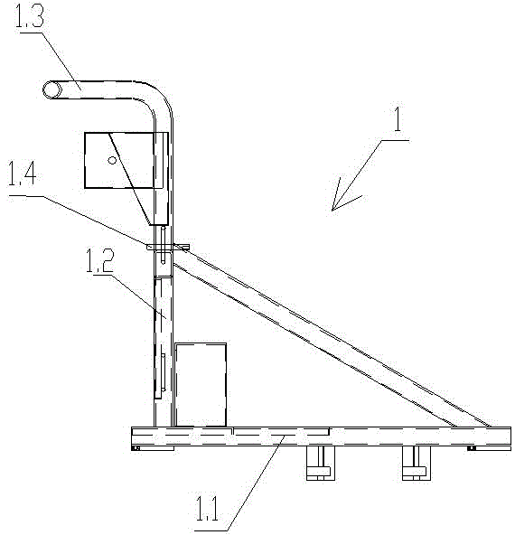
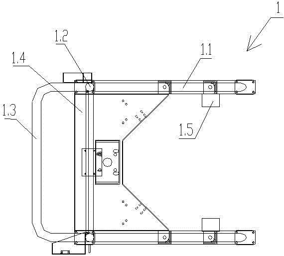
[0031] see Figure 1~4 , a mobile urea filling machine related to the present invention, the filling machine includes a vehicle frame 1, a clamping mechanism 2 and a power mechanism 3, the vehicle frame 1 includes a base 1.1, and the bottom of the base 1.1 is set There are rollers, the base 1.1 is provided with a U-shaped opening, and the base 1.1 is hinged with supporting pieces 1.5 on both sides of the U-shaped opening, a torsion spring is arranged between the supporting piece 1.5 and the base 1.1, and the vertical Two vertical rods 1.2 are installed upwards, a crosspiece 1.4 is connected between the two vertical rods 1.2, and a push handle 1.3 is installed on the top of the vertical rods 1.2;

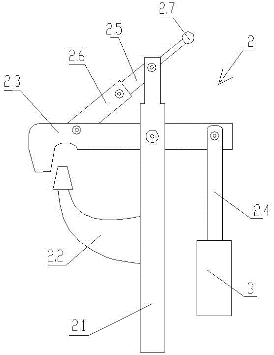
[0032] The clamping mechanism 2 includes a pillar 2.1 vertically installed on the vehicle frame 1, a clamping part 2.2 is connected to the pillar 2.1, and the pillar 2.1 is hinged to the middle part of a swing rod 2.3, and the swing rod One end of 2.3 is bent downwards and provided ...


PUM


Abstract

The invention provides a movable urea injection machine and a moving method thereof. The movable urea injection machine comprises a frame (1), a clamping mechanism (2) and a power mechanism (3). The frame (1) comprises a base (1.1). The bottom of the base (1.1) is provided with rolling wheels, supporting pieces (1.5) are hinged to the two sides of a U-shaped opening of the base (1.1), and torsional springs are arranged between the supporting pieces (1.5) and the base (1.1). The clamping mechanism (2) comprises a supporting column (2.1) vertically arranged on the frame (1). A clamping piece (2.2) is connected to the supporting column (2.1). The supporting column (2.1) is hinged to the middle of a swing rod (2.3). The bent end of the swing rod (2.3) is provided with a protruding block close to the top of the clamping piece (2.2). A connecting rod (2.4) is hinged to the other end of the swing rod (2.3) and connected with a power mechanism (3). By the adoption of the movable urea injection machine and the moving method thereof, use is convenient, and cost is low.

Description

technical field [0001] The invention relates to a mobile urea filling machine and a moving method thereof, belonging to the technical field of urea filling machines. Background technique [0002] At present, in order to obtain greater power and higher torque, trucks for logistics use diesel engines; in order to protect the environment and prevent diesel engines from polluting the atmosphere, it is necessary to reduce the nitrogen oxides emitted by diesel engines during work. Carry out digestion. At this time, use urea solution for vehicles as a reducing agent to reduce nitrogen oxides to nitrogen and water during the exhaust process, thereby avoiding pollution to the environment; [0003] Since the urea solution for vehicles is always consumed during use, it is necessary to add urea regularly, and the urea filling machine is the equipment used for filling urea; as disclosed in Chinese patent 201520294655. A fixed structure needs to be installed at a fixed location of the ga...

Claims


Application Information

Patent Timeline
Patent Type & Authority Applications(China)
IPC IPC(8): B67D7/02B67D7/16B67D7/58
CPCB67D7/02B67D7/16B67D7/58
Inventor 张辉孙传瑞钱鹏吴重菲周翔朱明玉
Owner JIANGYIN FUREN HIGH TECH
Learn More