An electric elastic plate active sound insulation actuator

An elastic plate and electric technology, which is applied in the direction of engine components, machines/engines, noise reduction devices, etc., can solve the problem of large axial length of electric actuators, limited service life of leaf springs, and greater influence of elastic plate structures, etc. problems, to achieve the effect of increasing the use method and scope, high utilization rate of magnetic energy, and compact structure

Active Publication Date: 2017-12-19
HARBIN ENG UNIV
View PDF6 Cites 0 Cited by
  • Summary
  • Abstract
  • Description
  • Claims
  • Application Information

AI Technical Summary

Problems solved by technology

However, the axial length of the electric actuator described in this technical solution is relatively large, and the overall mass is relatively large, and the lateral installation has a great influence on the structure of the elastic plate
The name is an electromagnetic actuator for active control of amorphous alloy transformer noise, and the patent publication number is CN103050216A. It has a simple structure and low manufacturing cost, but the electromagnetic actuator moving iron core and actuator The bases are only connected by leaf springs, and the lateral support is insufficient, resulting in limited service life of the leaf springs

Method used


Image

  • An electric elastic plate active sound insulation actuator
  • An electric elastic plate active sound insulation actuator
  • An electric elastic plate active sound insulation actuator

Examples


Embodiment Construction

[0020] The present invention is described in more detail below in conjunction with accompanying drawing example:

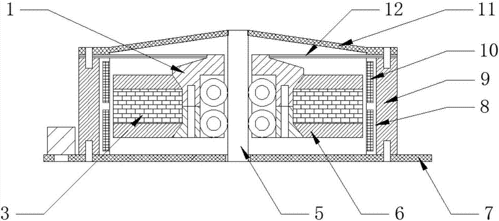
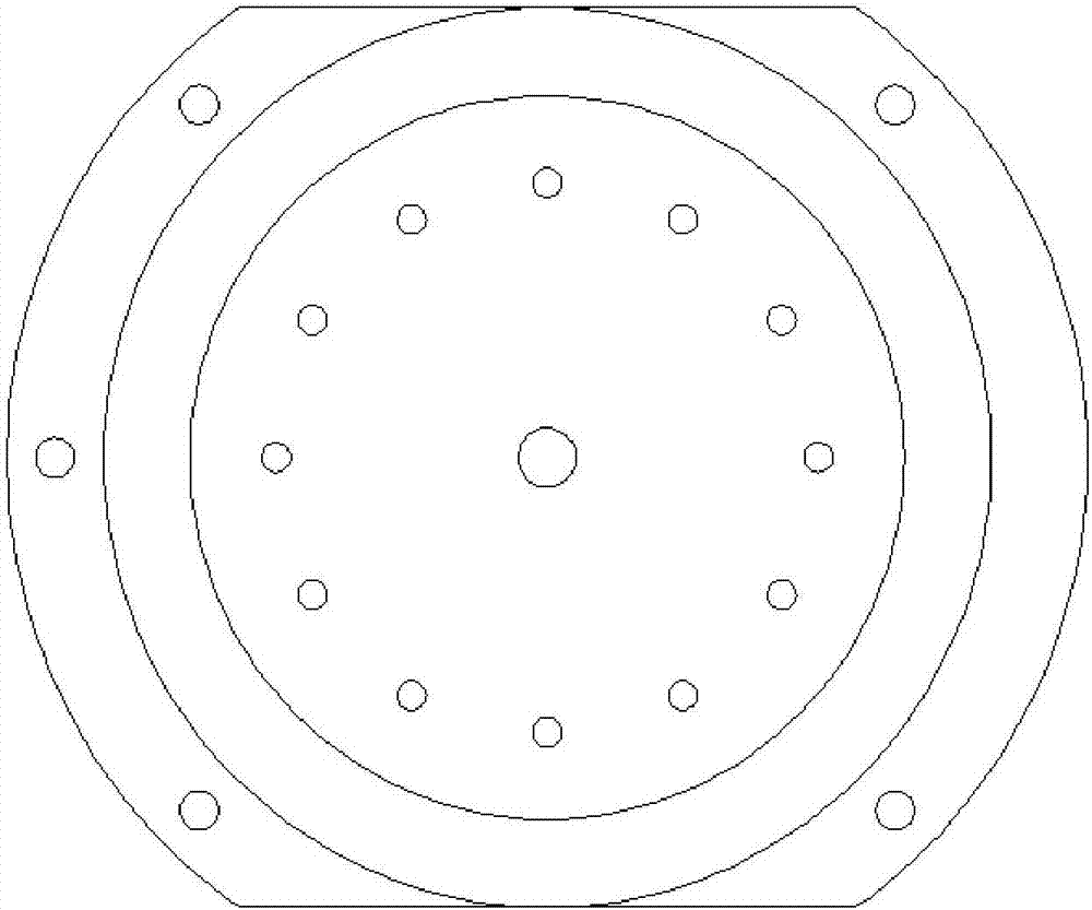
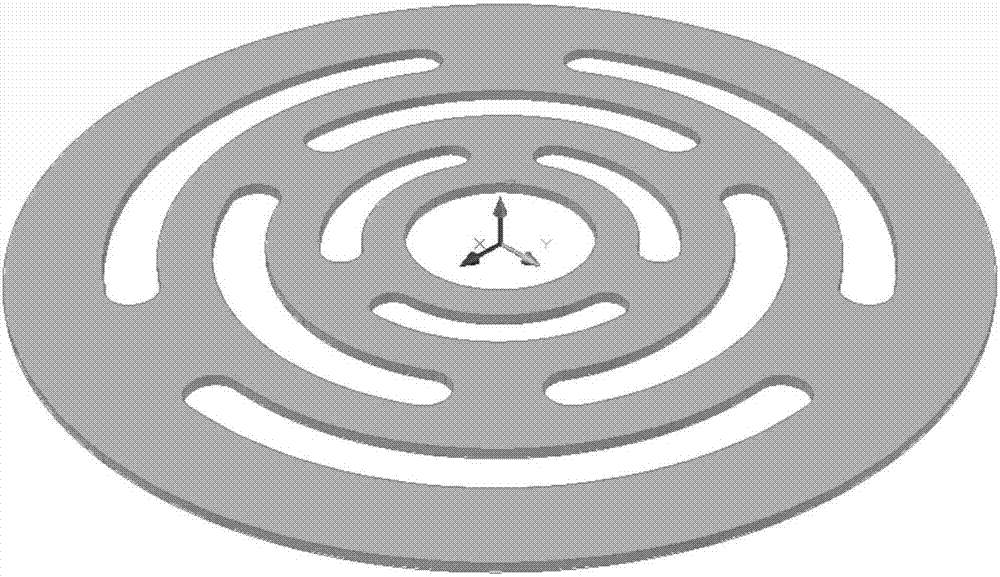
[0021] to combine Figure 1~3 , the present invention includes an annular permanent magnet, two upper and lower annular magnetic steels and an outer magnetic tube. The permanent magnet, magnetic steel and pulley assembly constitute the mass part of the mover, which is in contact with the central axis of the actuator through the guide wheel, and connected with the outer magnetic cylinder through the metal leaf spring. This embodiment also includes a coil and a coil holder, the coil is wound and embedded in the coil holder, and the outer wall of the annular coil holder cooperates with the inner wall of the outer magnetic tube. When the coil is energized, the mass part of the mover reciprocates under the action of the electromagnetic excitation force of the energized coil, thereby generating force to effectively implement the control of the controlled object and red...


PUM


Abstract

The invention aims at providing an electric active sound isolation actuator for an elastic plate. The electric active sound isolation actuator comprises an outer magnetic conducting cylinder, an upper end cover, a lower end cover, a permanent magnet, an upper armature, a lower armature, an upper pulley assembly and a lower pulley assembly, wherein the permanent magnet is arranged between the upper armature and the lower armature and forms a magnetic circuit together with the outer magnetic conducting cylinder. The upper armature, the lower armature and the permanent magnet are clamped by the upper pulley assembly and the lower pulley assembly and are fixed through bolts to form a mover part of the actuator. The upper end of the mover part is provided with a plate spring, and the outer end of the plate spring is arranged between the upper end cover and the outer magnetic conducting cylinder. The upper end cover is arranged at the upper end part of the outer magnetic conducting cylinder, the plate spring is fixedly arranged between the upper end cover and the outer magnetic conducting cylinder, and the lower end cover is arranged at the lower end part of the outer magnetic conducting cylinder. An upper coil and a lower coil are respectively wound on the inner wall of the outer magnetic conducting cylinder according to opposite directions. The electric active sound isolation actuator is compact in volume, large in output force and relatively high in work efficiency; and the mounting time and debugging time during control are shortened because the electric active sound isolation actuator can be used by only switching on a power source while being mounted.

Description

technical field [0001] The invention relates to a noise control device, specifically an electromagnetic actuator. Background technique [0002] According to different specific control methods, active noise control technology can be divided into active sound control and active force control. Before the 1990s, active control systems generally used sound sources (such as loudspeakers) to generate secondary sound fields for control. Therefore, this active control method is called active sound control, also known as "muffling noise with sound". The research on active sound control reached its peak in the mid-1980s to the mid-1990s, and the research of the Institute of Sound and Vibration (ISVR) of the University of Southampton in the UK was the most outstanding. The research results were mainly applied to the cabins of ships or aircraft, Automotive cabs and other workspace environments. [0003] In engineering practice, a considerable part of the noise is caused by structural ...

Claims


Application Information

Patent Timeline
Patent Type & Authority Patents(China)
IPC IPC(8): F01N13/00
CPCF01N13/00
Inventor 杜敬涛任可欣贺惠民杨铁军吴登峰
Owner HARBIN ENG UNIV
Why Eureka
Try Eureka