
Energy coupler applicable to cosine grating-loaded folded waveguide slow-wave structure

An energy-coupling, slow-wave structure technology, applied to the coupling device of the transit time type electron tube, etc., can solve the problems of poor matching, large impedance mismatch, unable to meet the requirements, etc., to achieve simple structure and realize input/output. Effect

Active Publication Date: 2016-04-06
NO 12 RES INST OF CETC
View PDF4 Cites 18 Cited by
  • Summary
  • Abstract
  • Description
  • Claims
  • Application Information

AI Technical Summary

Problems solved by technology

Compared with conventional slow-wave structure energy couplers, there is usually a large impedance mismatch when transitioning from a simple rectangular waveguide structure to a complex slow-wave structure
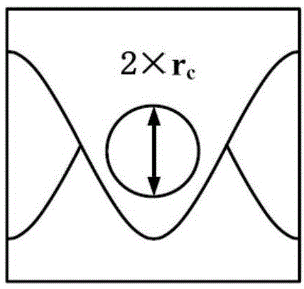
Figure 4 The direct transition from rectangular waveguide structure to Figures 2A-2C The voltage injection wave ratio when the cosine grid is loaded with the folded waveguide slow wave structure shows that the matching is very poor and cannot meet the requirements

Method used


Image

  • Energy coupler applicable to cosine grating-loaded folded waveguide slow-wave structure
  • Energy coupler applicable to cosine grating-loaded folded waveguide slow-wave structure
  • Energy coupler applicable to cosine grating-loaded folded waveguide slow-wave structure

Examples


example

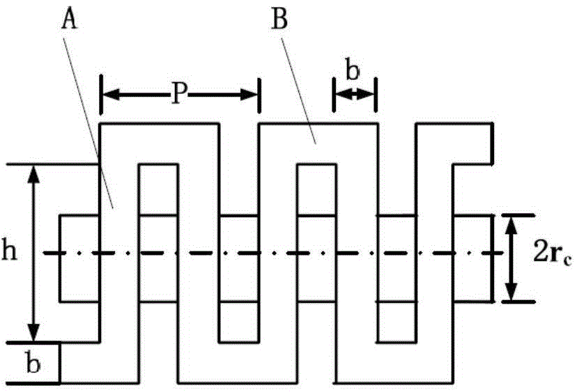
[0038] In the short millimeter wave region, the structural dimensions of a single electron beam channel cosine grid loaded folded waveguide slow wave structure are as follows (in mm): a=1.3, b=0.3, p=1.32, rc=0.18, Ac=0.33 . The structural size of the energy coupler according to the present invention is (unit: mm): the wide and narrow sides of the rectangular waveguide are a'=2.54 and b'=1.32 respectively, and the length, width and height of the metal ridge of the single-ridge waveguide section are l1' respectively =0.792, w'=0.5 and h'=0.4, the length of the tapered single ridge waveguide section ridge is l2'=0.53, the coupler has an electron injection channel structure which is connected with the slow wave structure and takes the centerline of the waveguide as the axis, corresponding to The electron beam channel radius is rc=0.18.

[0039] Figure 7 Match performance for high frequency systems using this example. The results obtained by the three-dimensional simulation so...


PUM


Abstract

The invention discloses an energy coupler applicable to a cosine grating-loaded folded waveguide slow-wave structure. The end surfaces, which are vertical to the axis of the slow-wave structure, of various gratings between adjacent straight waveguide sections in a folded waveguide, with a periodic structure, of the folded waveguide slow-wave structure have cosine profiles at one side of a waveguide connection segment. The energy coupler comprises a rectangular waveguide; andmetal ridges are formed on the rectangular waveguide corresponding to cosine profile gratings at one side of the cosine grating-loaded folded waveguide slow-wave structure. The energy coupler disclosed by the invention is simple in structure, and is connected with the input and output of the cosine grating-loaded folded waveguide slow-wave structure with a complicated structure to form a high-frequency system with the energy coupler, so that the effective input / output of an electromagnetic field from the rectangular waveguide can be achieved.

Description

technical field [0001] The invention belongs to the field of microwave vacuum electronic devices, and in particular relates to an energy coupler suitable for a cosine grid-loaded folded waveguide slow-wave structure. Background technique [0002] Traveling wave tube is an important electronic device used in contemporary national defense equipment and national economy. It has been widely used as the transmitting source of radio and television stations, as the transponder of microwave communication and satellite communication. In recent years, with the development of application requirements, traveling wave tubes are expanding to the direction of working in the millimeter wave or even terahertz frequency domain. The slow-wave structure as the core of the traveling wave tube has also received sufficient attention, among which the folded waveguide slow-wave structure and its deformation structure have been extensively and deeply studied. [0003] Processing technology plays a d...

Claims


Application Information

Patent Timeline
Patent Type & Authority Applications(China)
IPC IPC(8): H01J23/42
CPCH01J23/42
Inventor 蔡军冯进军邬显平
Owner NO 12 RES INST OF CETC
Learn More