High-thermal conductivity metal substrate, fabrication method thereof, LED module and fabrication method of LED module

A heat-conducting metal plate and metal substrate technology, applied in semiconductor devices, lighting and heating equipment, semiconductor devices of light-emitting elements, etc., can solve the problems affecting the quality of LED modules, low bonding force, etc., to speed up the efficiency of mass industrial production , Increase adhesion and ensure the effect of heat dissipation

Active Publication Date: 2016-04-06
RAYBEN TECH ZHUHAI
View PDF8 Cites 7 Cited by
  • Summary
  • Abstract
  • Description
  • Claims
  • Application Information

AI Technical Summary

Problems solved by technology

However, when a titanium film is formed on the surface of an aluminum substrate by a PVD (Physical Vapor Deposition) process, there is a problem of low bonding force between titanium and aluminum, which affects the quality of the LED module

Method used


Image

  • High-thermal conductivity metal substrate, fabrication method thereof, LED module and fabrication method of LED module
  • High-thermal conductivity metal substrate, fabrication method thereof, LED module and fabrication method of LED module
  • High-thermal conductivity metal substrate, fabrication method thereof, LED module and fabrication method of LED module

Examples


Embodiment Construction

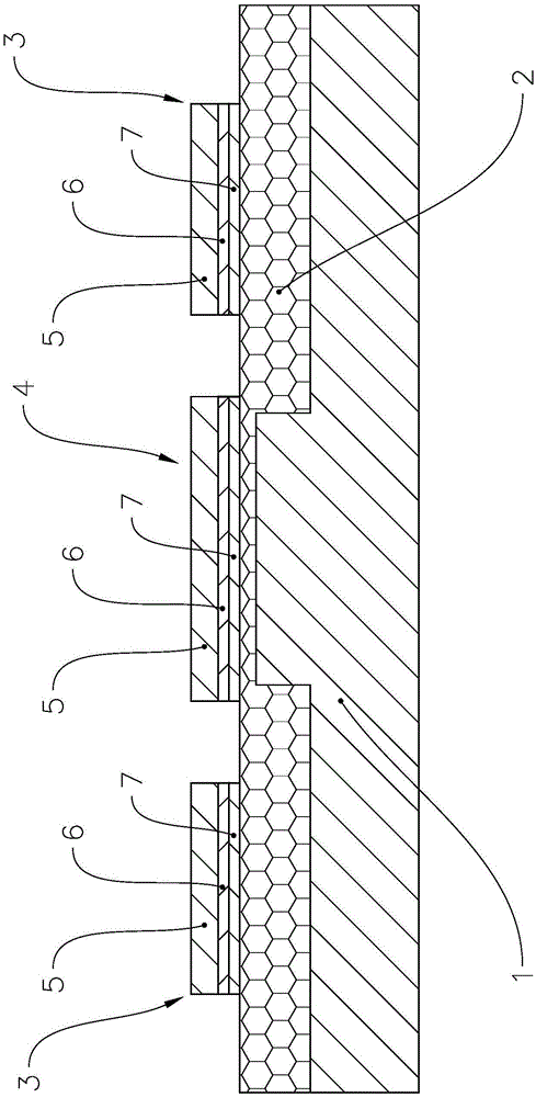
[0033] Such as figure 1As shown, the highly thermally conductive metal substrate of the present invention includes a thermally conductive metal plate 1 , preferably, the thermally conductive metal plate 1 is an aluminum substrate. A part of at least one surface of the heat-conducting metal plate 1 is oxidized to form an oxidized insulating layer 2 , and a conductive pattern layer 3 and a heat-conducting pad 4 are formed on the oxidized insulating layer 2 . The insulating oxide layer 2 on the surface covered by the heat conduction pad 4 is thinner than the insulating oxide layer 2 on the surface covered by the conductive pattern layer 3 . Preferably, the thickness of the insulating oxide layer 2 on the surface covered by the heat conduction pad 4 is 3 microns to 5 microns, and the thickness of the insulating oxide layer on the surface covered by the conductive pattern layer 3 is 35 microns to 50 microns. Wherein, the conductive pattern layer 3 and the heat conduction pad 5 bot...


PUM

PropertyMeasurementUnit
thicknessaaaaaaaaaa
thicknessaaaaaaaaaa
thicknessaaaaaaaaaa

Abstract

The invention provides a high-thermal conductivity metal substrate and a fabrication method thereof, an LED module and the fabrication method of the LED module. The high-thermal conductivity metal substrate comprises a heat-conducting metal plate, wherein one part of at least one surface of the heat-conducting metal plate is oxidized to form an oxidized insulating layer; a conductive pattern layer and a heat-conducting bonding pad are formed on the oxidized insulating layer; and the oxidized insulating layer on the surface covered by the heat-conducting bonding pad is thinner than the oxidized insulating layer on the surface covered by the conductive pattern layer. The fabrication method comprises the following steps: forming a surface coverage protecting film of the heat-conducting bonding pad on the heat-conducting metal plate; carrying out first anodic oxidation on the heat-conducting metal plate to form the oxidized insulating layer; after removing the protecting film, carrying out second anodic oxidation on the heat-conducting metal plate; forming a connecting metal layer and a conductive metal layer on the surface of one side, formed with the oxidized insulating layer, of the heat-conducting metal plate; and etching the connecting metal layer and the conductive metal layer to obtain a circuit pattern and the heat-conducting bonding pad. According to the LED module provided by the invention, the cooling effect can be improved; and the service lifetime can be prolonged.

Description

technical field [0001] The invention relates to the field of LED lamps, in particular to a high thermal conductivity metal substrate applied to an LED module and a manufacturing method thereof, and also to an LED module applying the high thermal conductivity metal substrate and a manufacturing method thereof. Background technique [0002] The LED module has a substrate on which LED light-emitting elements are arranged. Usually, the substrate is a ceramic substrate or a metal substrate. Since LED light-emitting elements generate a large amount of heat during operation, the substrate needs to have good heat conduction and heat dissipation capabilities. In order to achieve a good heat dissipation effect, the traditional thermoelectric separation substrate adopts a scheme in which two electrodes and a heat sink are arranged on the same horizontal plane of the substrate. This solution, due to product design, has the defect of height difference between the electrode pad and the h...

Claims


Application Information

Patent Timeline
Patent Type & Authority Applications(China)
IPC IPC(8): H01L33/64H01L33/62F21V19/00F21V29/89F21Y115/10
CPCF21V19/001H01L33/62H01L33/641H01L33/647H01L2933/0066H01L2933/0075
Inventor 李保忠肖永龙林伟健
Owner RAYBEN TECH ZHUHAI
Why Eureka
Try Eureka