Rotating shaft structure of permanent magnet motor and assembling method of the rotating shaft structure

A technology of rotating shaft structure and permanent magnet motor, which is applied in the direction of magnetic circuit shape/style/structure, magnetic circuit rotating parts, etc., can solve the problems affecting the structural strength of the rotating shaft, inconvenient assembly and maintenance, and inconvenient maintenance, etc., to achieve improvement Ease of assembly, simple assembly, and convenient maintenance

Inactive Publication Date: 2016-04-06
GREE ELECTRIC APPLIANCES INC
View PDF6 Cites 11 Cited by
  • Summary
  • Abstract
  • Description
  • Claims
  • Application Information

AI Technical Summary

Problems solved by technology

[0004] The above-mentioned three-stage high-speed rotor structure is complex in structure, inconvenient for assembly and maintenance, and also affects the structural strength of the shaft to a certain extent.
[0005] In the prior art, there are defects such as complex structure, low strength and inconvenient maintenance

Method used


Image

  • Rotating shaft structure of permanent magnet motor and assembling method of the rotating shaft structure
  • Rotating shaft structure of permanent magnet motor and assembling method of the rotating shaft structure
  • Rotating shaft structure of permanent magnet motor and assembling method of the rotating shaft structure

Examples


Embodiment Construction

[0034] In order to make the purpose, technical solution and advantages of the present invention clearer, the technical solution of the present invention will be clearly and completely described below in conjunction with specific embodiments of the present invention and corresponding drawings. Apparently, the described embodiments are only some of the embodiments of the present invention, but not all of them. Based on the embodiments of the present invention, all other embodiments obtained by persons of ordinary skill in the art without making creative efforts belong to the protection scope of the present invention.

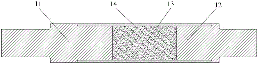
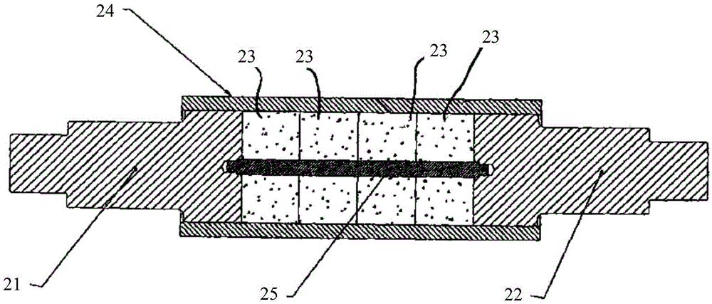
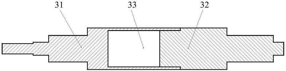
[0035] According to an embodiment of the present invention, a permanent magnet motor shaft structure is provided. The shaft structure includes:

[0036] The first rotating shaft end piece 31, the magnetic core and the second rotating shaft end piece 32; wherein, one end of the first rotating shaft end piece 31 is provided with an accommodating cavity; the accommo...


PUM


Abstract

The invention discloses a rotating shaft structure of a permanent magnet motor and an assembling method of the rotating shaft. The rotating shaft structure comprises a first rotating shaft end part, a magnetic core and a second rotating shaft end part, wherein an accommodating cavity is arranged at one end of the first rotating shaft end part, is used for accommodating the magnetic core and is connected with the second rotating shaft end part. According to the scheme provided by the invention, such defects in the prior art as complicated structure, low strength and inconvenient maintenance can be overcome and the advantages of simple structure, high strength and convenient maintenance can be achieved.

Description

technical field [0001] The present invention relates to the technical field of motors, in particular to a shaft structure of a permanent magnet motor and an assembly method thereof, in particular to a shaft structure of a two-stage high-speed permanent magnet motor and an assembly method thereof. Background technique [0002] Generally, a rotor whose speed is above 1000 rpm or exceeds the first-order critical speed of the rotor can be regarded as a high-speed rotor. see figure 1 , in the rotor shaft of the high-speed permanent magnet motor with the patent application number "98802132.3", the shaft is spliced ​​by three sections, and the whole cylindrical magnetic steel is used, and the torque is transmitted by the interference fit between the alloy sheath 14 and the three-section main shaft . Wherein, both the first rotating shaft end piece 11 and the second rotating shaft end piece 12 are made of non-magnetic conductive material, and a cylindrical magnetic steel 13 is for...

Claims


Application Information

Patent Timeline
Patent Type & Authority Applications(China)
IPC IPC(8): H02K1/22
CPCH02K1/22
Inventor 贾金信胡余生刘健宁张芳张小波钟成堡郭长光李广海
Owner GREE ELECTRIC APPLIANCES INC
Why Eureka
Try Eureka