Imaging device and positioning device
一种成像设备、成像装置的技术,应用在定位、测量装置、医学图像等方向,达到改善健康检查能力、增加工作效率、节省准备时间的效果
- Summary
- Abstract
- Description
- Claims
- Application Information
AI Technical Summary
Problems solved by technology
Method used
Image

Examples
no. 1 approach
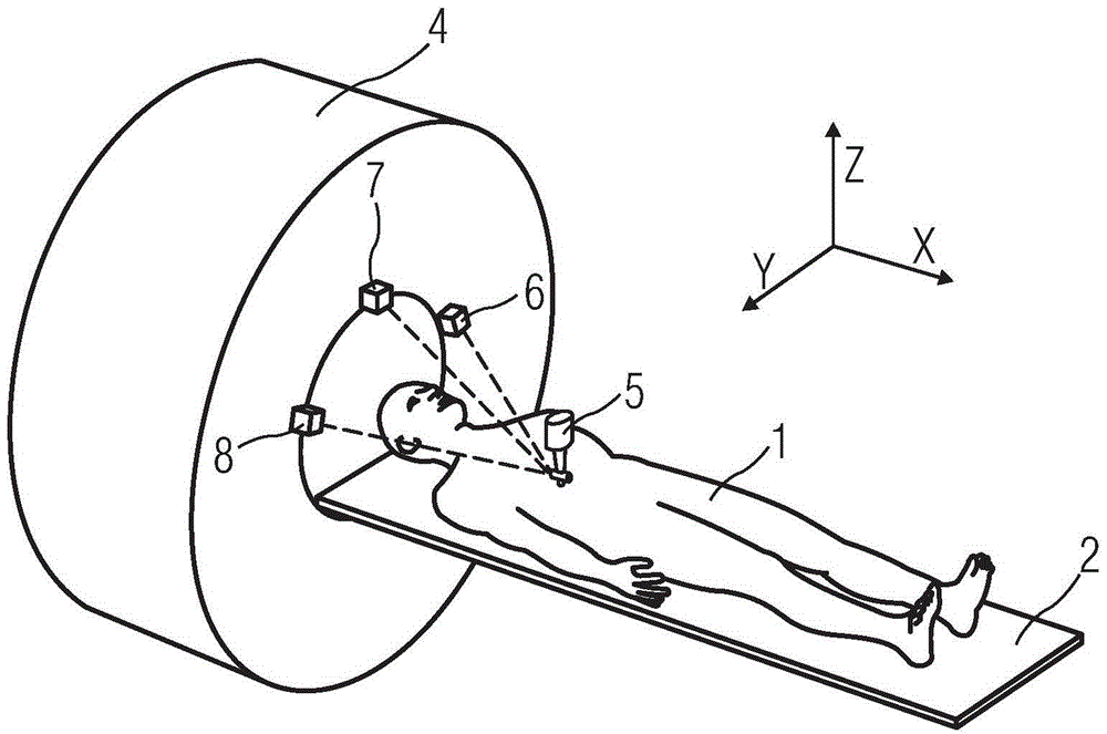
[0046] figure 1 A schematic diagram of an image forming apparatus to which the first embodiment of the present invention is applied is shown. figure 1 In , a magnetic resonance (MR) imaging device is taken as an example for illustration. The imaging device includes, for example: an examination table 2 on which the subject 1 is placed; a distance positioning device for positioning the detected part 3 of the subject 1; Region of the imaging device (magnet) 4 . In this embodiment, the subject 1 lies on the examination bed 2, and the distance between the detected part 3 of the subject 1 and the imaging device 4 is determined by the distance positioning device, and then the examination bed 2 transports the subject 1 into the imaging device 4, and align the detected part 3 with the imaging area of the imaging device 4 according to the position determined by the distance positioning device, and make the imaging device 4 image the detected part 3.
[0047] The distance locating...
no. 2 approach
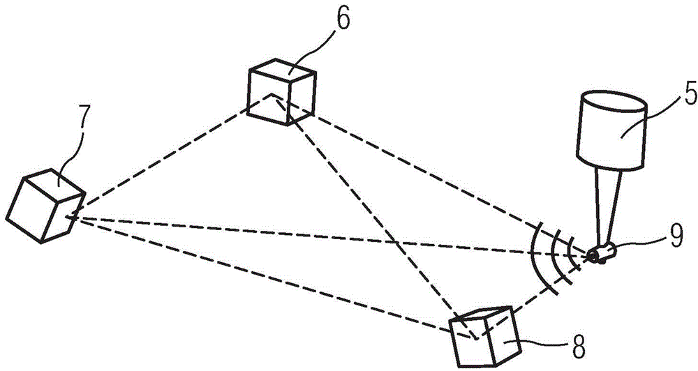
[0061] In daily diagnostic health checks, in the imaging of the imaging device, not only images in the vertical direction are provided, but sometimes they are rotated or flipped at a certain angle for easier diagnosis. In this case, on the basis of the above-mentioned first embodiment, this embodiment also provides an angle positioning device capable of detecting the rotation and flip angles of the indicator 5 in space. Refer to the attached Figure 7 , the configuration and angle detection of the angle positioning device according to this embodiment will be described. Figure 7 A structural diagram of the angle positioning device is shown. The angle positioning device has the same structure as the first embodiment except that the structure of the indicator 5 is different from the first embodiment.
[0062] Such as Figure 7 As shown, in the indicator 5 of this embodiment, in addition to the signal generator 9 , an auxiliary signal generator 13 is also provided on the side ...
no. 3 approach
[0070] In the above-mentioned first and second embodiments, it was exemplified that three signal detectors 6, 7, 8 are provided in the imaging device, and one signal generator 9 is provided in the detected part of the subject, but it is not limited to Here, for example, in the case of a plurality of detected parts, different from the above-mentioned embodiment, a plurality of, for example, three signal generators 9 may be provided, and the three signal generators 9 may be arranged in a predetermined positional relationship. In the imaging device, a plurality of signal detectors corresponding to the number of the plurality of detected parts are provided on the detected parts. For example, three signal generators arranged on the imaging device sequentially send out ultrasonic signals, which are received by multiple signal detectors, so as to determine the positions of the multiple signal detectors relative to the signal generators, and then determine multiple detected signals. T...
PUM
 Abstract
Description
Claims
Application Information
 - R&D
- Intellectual Property
- Life Sciences
- Materials
- Tech Scout
- Unparalleled Data Quality
- Higher Quality Content
- 60% Fewer Hallucinations
Browse by: Latest US Patents, China's latest patents, Technical Efficacy Thesaurus, Application Domain, Technology Topic, Popular Technical Reports.
© 2025 PatSnap. All rights reserved.Legal|Privacy policy|Modern Slavery Act Transparency Statement|Sitemap|About US| Contact US: help@patsnap.com